CT selection to extend measurement limits
How to choose the right one current transformer for extending the measurement limits of ammeters in alternating current circuits.
When measuring alternating current with an ammeter, the readings at the end of the scale of the device should be read. If the value of the measured current is less than the upper measurement limit indicated on the device, then the latter is connected directly to the network in series with the load.
If the measured current is greater than the upper measurement limit indicated on the device, then a measuring current transformer is usually used to extend the measurement limits.
Knowing the nominal transformation ratio of the current transformer KnAz and reading the ammeter I2, you can determine the strength of the measured current: I1 = I2 NS KnAz
When measuring large currents, the primary winding of the current transformer is connected in series to the circuit of the measured current, and an ammeter with a low resistance (not more than 2 ohms) is connected to the secondary winding.The limit value of the resistance to which the secondary winding can be closed is indicated in the passport of the current transformer. The ammeter is usually rated at 5 A. The secondary winding of the current transformer is grounded.
The measuring current transformer is selected depending on the operating conditions and the value of the measured current... For example, if you want to measure a current of the order of 80 A, then you should take a current transformer designed for a rated primary current of 100 A, i.e. KnAz = 100/5 = 20. Suppose the ammeter reading is 3.8 A, then effective value of the measured currentI1 = 3.8 x 20 = 76 A.
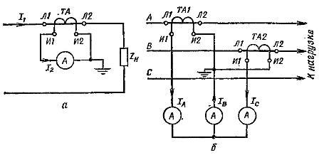
Schemes for switching on ammeters with measuring current transformers: o — in a single-phase network, b — in a three-phase network.
Portable current transformers are usually multi-rated. Their primary winding has either several sections connected in series, parallel or mixed (which changes the measurement limit), or taps are made from it.
To further expand the limits of measurement, the cases of portable current transformers have a window through which you can wind the required number of turns with a wire connecting the measuring circuit, thereby creating turns on the primary winding.
The number of turns and the cross-sectional area of the cable of the primary winding depend on the value of the measured current, they are determined by the table located on the front side of the current transformer. Make sure that the total resistance of the wires connected to the secondary winding does not exceed the value indicated on the nameplate of the current transformer.
When working with measuring current transformers, it is necessary to ensure that the secondary winding does not remain open when the primary is connected.
If the load changes within narrow limits, then you can take a certain measuring current transformer, for example, type TK in low voltage and type TPOL-10 in a high voltage network.
If the measured currents do not exceed 50 A, then it is convenient to use universal current transformers type I54 having seven primary rated currents: 0.5; 1.0; 2; 5; ten; twenty; 50 A and a secondary rated current of 5 A. As you can see, the measuring current transformer can not only reduce the current, but also increase it. For example, at a rated current of 0.5 A, the measuring current transformer increases the primary current by a factor of 10.
If in a low-voltage network the measured currents reach 600 A, then in this case universal measuring current transformers of the UTT type are convenient, which have their own primary winding, designed for currents of 15 and 50 A, and can have an external winding of the core at large currents. The number of turns is selected according to the table attached to the transformer. By changing the number of coil turns, different rated currents can be set.
A very convenient measuring clamp, which differs from measuring current transformers by the presence of a detachable magnetic circuit, which makes it possible to measure the current in the wires without breaking them beforehand. The measuring clamp is connected to the circuit only during the measurement. Their main disadvantage is the lower measurement accuracy.