Low power synchronous motors
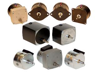
Low-power synchronous electric motors (micromotors) used in automation systems, various household appliances, clocks, cameras, etc.
Most synchronous electric motors of low power differ from machines of normal performance only in the design of the rotor, which, as a rule, does not have a field winding, slip rings and brushes pressed against them.
To generate torque, the rotor is made of a hard magnetic alloy, followed by single magnetization in a strong pulsed magnetic field, as a result of which the poles subsequently retain residual magnetization.
When a soft magnetic material is used, the rotor receives a special shape that provides different magnetic resistance to its magnetic core in radial directions.
At the time of starting, the synchronous motor operates as an induction motor, and its initial torque is created due to the interaction of the rotating magnetic field of the stator with the currents induced by it in the short-circuited rotor winding. As the motor is started in the excited state, the magnetic field of the permanent magnets of the rotating rotor induces e in the stator winding. etc. v. variable frequency and this causes currents due to which braking torque occurs.
The resulting torque on the motor shaft is determined by the sum of the moments due to the short circuit of the winding and the braking effect, i.e. which depends on the slip. During the acceleration of the rotor, this torque reaches a minimum value, which, with the correct selection of the starting winding, should be greater than the nominal torque.
When the speed approaches synchronous, the rotor, as a result of the interaction of the field of permanent magnets with the rotating magnetic field of the stator, is pulled into synchronism and then rotates at synchronous speed.
The operation of a permanent magnet synchronous motor differs little from that of a wound synchronous motor.
 Synchronous resistance motors have a salient pole rotor made of a soft magnetic material with cavities or slits, so its magnetic resistance in radial directions is different. The hollow rotor consists of stamped sheets of electrical steel and has a short-circuited starting coil. There are rotors made of solid ferromagnetic material with similar cavities.The sectional rotor consists of sheets of electrical steel cast with aluminum or other diamagnetic material, which acts as a short circuit winding.
When the stator winding is switched on, a rotating magnetic field is spun and the motor starts asynchronously. After completing the acceleration of the rotor to the synchronous speed, under the action of the reactive torque due to the difference in magnetic resistance in the radial directions, it enters into synchronism and is located relative to the rotating magnetic field of the stator, so that its magnetic resistance to this field is the most - the little one.
 Commonly, synchronous resistance motors are produced with rated power up to 100 W, and sometimes even higher if they attach particular importance to simplicity of design and increased reliability. With the same dimensions, the rated power of synchronous resistance motors is 2 — 3 times less than the rated power of permanent magnet synchronous motors, but they are simpler in design, differ in lower cost, their rated power factor does not exceeds 0.5 and the nominal efficiency is up to 0.35 — 0.40.
Hysteresis synchronous motors have a hard magnetic alloy rotor with a wide hysteresis loop… To save this expensive material, the rotor is made of a modular construction, in which the shaft is attached to a sleeve made of ferro- or diamagnetic material, and is a reinforced solid or hollow cylinder assembled from plates tightened with a locking ring on it .The use of a hard magnetic alloy for the manufacture of the rotor leads to the fact that when the motor is running, the magnetic induction distribution waves on the surfaces of the stator and the rotor are shifted relative to each other at a certain angle, called the hysteresis angle, which causes the appearance of a hysteresis torque, directed to the rotation of the rotor.
The difference between permanent magnet synchronous motors and hysteresis synchronous motors is that in the former the rotor is pre-magnetized in a strong pulsed magnetic field during machine manufacturing, and in the latter it is magnetized by the rotating magnetic field of the stator.
When starting a synchronous motor with hysteresis, in addition to the main hysteresis moment in machines with a solid rotor, an asynchronous torque occurs due to eddy currents in the rotor magnetic circuit, which contributes to the acceleration of the rotor, its entry into synchronism and further operation at synchronous speed with constant displacement of the rotor relative to the rotating magnetic field of the stator by an angle determined by the load on the machine shaft.
Hysteresis synchronous motors operate in both synchronous and asynchronous modes, but in the latter case with low slip. Synchronous motors with hysteresis are distinguished by a large starting torque, smooth entry into synchronism, a slight change in current within 20-30% during the transition from idle mode to short-circuit mode.
These motors have better performance than synchronous reluctance motors, are distinguished by the simplicity of design, reliability and silent operation, small size and low weight.
The absence of a short winding causes the rotor to oscillate under variable load, which leads to a certain unevenness of its rotation, which limits the range of applications of machines that are manufactured with a rated power of up to 400 W for industrial and increased frequencies, both single and double speeds.
The rated power factor of hysteresis synchronous motors does not exceed 0.5, and the rated efficiency reaches 0.65.
When turning on the stator winding, due to the short-circuited turns, a phase shift is created in time between the magnetic fluxes of the unshielded and shielded parts of the poles, which leads to the excitation of the resulting rotating magnetic field. This field interacting with the rotor contributes to the appearance of asynchronous and hysteresis torques, causing the acceleration of the rotor, which, upon reaching the synchronous speed, under the influence of reactive and hysteresis torques, enters into synchronism and rotates in the direction from the unshielded part of the pole to its shielded part where the short circuit turns.
I have reversible motors, instead of short-circuiting, four windings are used, which are located on the two parts of each split pole, and for the accepted direction of rotation of the rotor, the corresponding pair of windings is short-circuited.
Reactive hysteresis synchronous motors have relatively large dimensions and weight, their nominal power does not exceed 12 μW, they operate at a very low power factor, and their nominal efficiency does not exceed 0.01.
Synchronous stepper motors control electrical impulses are converted into a set angle of rotation, implemented in a discrete manner. They have a stator, on the magnetic circuit of which there are two or three identical spatially displaced coils connected in series to a source of electrical energy in the form of rectangular pulses adjustable frequency. Under the influence of current pulses, the poles of the stator are respectively magnetized with variable polarity. The change in the direction of the currents in the stator windings leads to a corresponding reversal of the magnetization of the poles and the establishment of a new opposite polarity.
The salient pole rotor of stepper motors can be active and reactive. An active rotor has a direct current field coil, slip rings and brushes or a system of permanent magnets with alternating polarity, and a reactive rotor is implemented without a field coil.
The number of poles on the rotor of a stepper motor is half the number of poles on the stator. Each switching of the stator windings rotates the resulting magnetic field of the machine and causes the rotor to move synchronously by one step.The direction of rotation of the rotor depends on the polarity of the pulse applied to the corresponding stator winding.