Basic parameters and characteristics of electromagnetic relays
 An electrical apparatus that applies the relay control law is called a relay... In a relay, when the control (input) parameter is smoothly changed to a certain set value, the controlled (output) parameter changes abruptly. Also, at least one of these parameters must be electrical.
Action of functional organs electromagnetic relay can be traced according to the diagram in fig. 1. The receiving body A converts the input value (voltage) Uin supplied to the coil 2 of the magnetic circuit 1 into an intermediate value, i.e. in the mechanical force of the anchor 3. The mechanical force of the anchor FЯ acts on the contact system of the executive body B. The intermediate value — the force of the anchor FЯ, is proportional to the input value Uin, is compared with a given value of the force Fpr developed by the spring 9 of the intermediate body B. When Uin <Uav, Fya
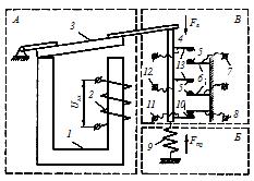 Rice. 1 Scheme of the electromagnetic relay
In the process of operation, the electromagnetic relay on a time scale distinguishes four phases: the period (time) of actuation tav, the working period twork, the period (time) of shutdown toff, the period (time) of rest tp (Fig. 2).
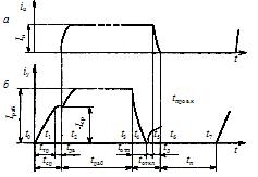
Rice. 2. Dependence of the quantities of output (a) and output (b) on time
Actuation period of an electromagnetic relay
 The response period includes the time interval from the moment the input signal begins to affect the monitoring body until the signal appears in the controlled circuit. The segment of the abscissa axis tav = t2 –t0 corresponds to this period in fig. 2, b. At the moment t0 the current in the relay coil increases to a value at which the electromagnetic force Fe acting on the armature begins to oppose the spring force Fm (mechanical force) of the intermediate body. The input value is then called the acceptance value.
The initial period corresponds to the segment ttr = t1 — t0. At time t1, the armature of the relay electromagnet starts to move. During tdv = t2 — t1, the anchor moves, overcoming the resistance of the intermediate body B (see Fig. 1) and activating the executive body C.
At the end of the armature stroke, the drive contacts close, the load current in (Fig. 2, a) begins to increase from zero to an equilibrium value. The input value at which control of the output circuit begins is called the acceptance value (Iav). The power Psr corresponding to Isr is called the actuating power.
Response time t cf = ttr + tdv.
The response time of electromagnetic relays varies from 1-2 to 20 ms. Electromagnetic time relays provide a delay of up to 10 s.
To estimate the response time of the relay, it is permissible to use the expression
t cf = t1kz-bm –a,
where t1 is the response time for a given safety factor ks and factor m = 1; a, b — coefficients that are determined depending on the type of relay and the values of kz and m.
For high-speed relays at kz = 1.5¸2, the value of the coefficient a approaches unity. For ordinary relays with k z = 1.5¸3, the value a = 0.25¸0.95, the value of the coefficient b is usually in the range 1.4-1.6.
Operating period of the electromagnetic relay
 The working period includes the time interval twork = t3 — t2, i.e. the time from the moment of control of the output circuit t2 to the moment of termination of the impact on the sensitive organ of the input signal t3. The current begins to rise to a stationary value of Iwork (Fig. 2, b) — this is the working value of the input value, which ensures reliable operation of the relay.
The ratio Iwork / Icr = kz is called the factor of safety at work.
To characterize the overload capacity of the sensitive element of the relay, the value of the input quantity is used, which is called the limit value of the operating quantity Ioperating.max.
Limitation of the working value — this is its value that the sensitive organ can withstand for a short normalized period of time. However, the value of this value is unacceptable when the relay is operating in normal mode due to the condition of electrical or mechanical strength or heating.
The control power concept Ru is used to characterize the load carrying capacity of the relay drive. Control power is the power in the controlled circuit that the drive can transmit for a long time.
Electromagnetic relay trip period
 The off period contains the time interval toff = t6 — t3, i.e. the time from the moment of cessation of the impact on the perceiving organ t3 to the moment when the current in the controlled circuit decreases to zero (Fig. 16, a).
The off period includes the release period totp = t4 — t3 in which the relay is off. The current iy in the relay coil drops to zero (Fig. 2, b). During this period, the opposing spring force (mechanical force) exceeds the electromagnetic force, i.e. Fm> Fe and the armature is released.
After selecting a contact failure (interval tc = t5 — t4), the relay contacts open and an arc is ignited between them, which extinguishes after time td = t6 — t5. During the period td, the current in the controlled circuit decreases from In to zero (Fig. 2, a).
Off time t t = tp + tc + td.
The tripping period is characterized by a recovery factor, which is the ratio of the drop current Iotp to the pickup current Iav: kv = Iotp / Icr.
Typically, for power system protection relays and control relays that control the input parameter within narrow limits, kv should be closer to unity.
Rest period of the electromagnetic relay
The rest period is the time interval tp = t7 — t6.
The latency period is characterized by a parameter called the inoperative value, which is the largest value of the input quantity ensuring that the relay does not operate or is held. The shutdown time is shorter than the operating start-up time and the release time.
The ratio of control power to actuation power is called gain, ku = Py / Pcr.
The number of starts per unit time is determined by a value that is inversely proportional to the cycle time:
f = 1 / tq = 1 / (Tsrab +Trob + Toff +TNS)
Lakota O.B.