Features of measuring small and large resistances
 Resistance is one of the most important parameters electrical circuitdetermining the operation of any circuit or plant.
Obtaining certain resistance values in the production of electrical machines, apparatus, devices during the installation and operation of electrical installations is a prerequisite for ensuring their normal operation.
Some resistances retain their value practically unchanged, while others, on the contrary, are highly susceptible to change from time to time, from temperature, humidity, mechanical effort, etc. Therefore, both in the manufacture of electrical machines, apparatus, devices, and in During installation, electrical installations must inevitably measure resistance.
The conditions and requirements for making resistance measurements are very diverse. In some cases, high accuracy is required, in others, on the contrary, it is enough to find an approximate value of the resistance.
Depending on the value electrical resistances are divided into three groups:
- 1 ohm and less — low resistance,
- from 1 ohm to 0.1 Mohm — medium resistances,
- of 0.1 Mohm and more — high resistances.
When measuring low resistance, it is necessary to take measures to eliminate the influence on the result of the measurement of the resistance of connecting wires, contacts and thermo-EMF.
When measuring average resistances, you can ignore the resistances of connecting wires and contacts, you can ignore the influence of insulation resistance.
When measuring high resistances, it is necessary to take into account the presence of volume and surface resistance, the influence of temperature, humidity and other factors.
Low resistance measurement characteristics
The group of small resistances includes: armature windings of electric machines, resistances of ammeters, shunts, resistances of windings of current transformers, resistance of short conductors of the bus, etc.
When measuring low resistances, you should always take into account the possibility that the resistance of the connecting wires and transient resistances can affect the measurement result.
Test lead resistances are 1 x 10⁴ — 1 x 10² ohm, junction resistance — 1 x 10⁵ — 1 x 10² ohm
At transient resistances or contact resistances understand the resistances that an electric current encounters when passing from one wire to another.
Transient resistances depend on the size of the contact surface, on its nature and condition — smooth or rough, clean or dirty, as well as on the density of contact, pressing force, etc.Let's understand, using an example, the influence of transition resistances and resistances of connecting wires on the measurement result.
In fig. 1 is a diagram for measuring resistance using example ammeter and voltmeter instruments.
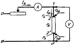
Rice. 1. Wrong wiring diagram for measuring low resistance with ammeter and voltmeter.
Say the required resistance rx — 0.1 ohm and the voltmeter resistance rv = 500 ohms. Since they are connected in parallel, then rNS/ rv= Iv / Ix = 0, 1/500 = 0.0002, ie the current in the voltmeter is 0.02% of the current in the desired resistance. Thus, with an accuracy of 0.02%, the ammeter current can be considered equal to the current in the required resistance.
Dividing the readings of the voltmeter connected to points 1, 1′ of the reading of the ammeter we get: U'v / Ia = r'x = rNS + 2рNS + 2рk, where r'x is the found value of the required resistance; rpr is the resistance of the connecting wire; gk — contact resistance.
Considering rNS =rk = 0.01 ohm, we get the measurement result r'x = 0.14 ohm, whence the measurement error due to the resistances of the connecting wires and contact resistances equal to 40% — ((0.14 — 0 .1) / 0.1)) x 100%.
It is necessary to pay attention to the fact that with a decrease in the required resistance, the measurement error due to the above reasons increases.
By connecting a voltmeter to the current clamps — points 2 — 2 in fig.1, that is, to those terminals of resistance rx to which the wires of the current circuit are connected, we get the reading of the voltmeter U «v less than U'v from the amount of voltage drop in the connecting wires and therefore the found value of the desired resistance rx «= U»v / Ia = rx + 2 rk will contain an error due only to the contact resistances.
By connecting a voltmeter as shown in fig. 2, to the potential terminals located between the current ones, we get the readings of the voltmeter U»'v is less than U «v of the size of the voltage drop across the contact resistances, and therefore the found value of the required resistance r » 'x = U»v / Ia = rx
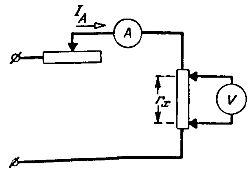
Rice. 2. The correct connection diagram for measuring small resistances with an ammeter and a voltmeter
Thus the value found will be equal to the actual value of the required resistance, since the voltmeter will measure the actual value of the voltage across the required resistance rx between its potential terminals.
The use of two pairs of clamps, current and potential, is the main technique to eliminate the influence of the resistance of the connecting wires and transient resistances on the result of the measurement of small resistances.
Characteristics of measuring high resistances
Bad current conductors and insulators have high resistance. When measuring the resistance of wires with low electrical conductivity, insulation materials and products made from them must take into account factors that can affect the degree of their resistance.
These factors mainly include temperature, for example the conductivity of electrical cardboard at a temperature of 20 ° C is 1.64 x 10⁻¹³ 1 / ohm and at a temperature of 40 ° C 21.3 x 10⁻¹³ 1 / ohm. Thus, a temperature change of 20 °C caused a 13-fold change in resistance (conductivity)!
The figures clearly show how dangerous it is to underestimate the influence of temperature on measurement results. Likewise, a very important factor affecting the magnitude of resistance is the moisture content of both the test material and the air.
Also, the type of current with which the test is conducted, the magnitude of the voltage being tested, the duration of the voltage, etc., can affect the resistance value.
When measuring the resistance of insulating materials and products made from them, the possibility of current passing through two paths must also be taken into account:
1) by the volume of the tested material,
2) on the surface of the tested material.
The ability of a material to conduct an electric current in one way or another is characterized by the amount of resistance that the current encounters in this joke.
Accordingly, there are two concepts: volume resistivity attributed to 1 cm3 of the material and surface resistivity attributed to 1 cm2 of the surface of the material.
Let us take an example for illustration.
When measuring the insulation resistance of a cable using a galvanometer, large errors can occur due to the fact that the galvanometer can measure (Fig. 3):
a) current Ivpassing from the core of the cable to its metal sheath through the volume of the insulation (current Iv due to the volume resistance of the cable insulation characterizes the insulation resistance of the cable),
b) current Epassing from the core of the cable to its sheath along the surface of the insulating layer (Because the surface resistance depends not only on the properties of the insulating material, but also on the condition of its surface).
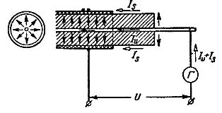
Rice. 3. Surface and volume current in the cable
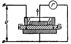
To eliminate the influence of conductive surfaces when measuring the insulation resistance, a coil of wire (safety ring) is applied to the insulation layer, which is connected as shown in Fig. 4.
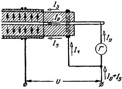
Rice. 4. Scheme for measuring the volume current of the cable
Then the current Is will pass in addition to the galvanometer and will not introduce errors into the measurement results.
In fig. 5 is a schematic diagram for determining the bulk resistivity of an insulating material. — plates A. Here BB — electrodes to which voltage U is applied, G — galvanometer measuring the current due to the volume resistance of plate A, V — protective ring.
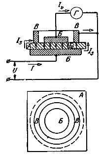
Rice. 5. Measurement of volume resistance of a solid dielectric
In fig. 6 is a schematic diagram for determining the surface resistance of an insulating material (plate A).
Rice. 6. Measurement of the surface resistance of a solid dielectric
When measuring high resistances, serious attention must also be paid to the insulation of the measuring installation itself, because otherwise a current will flow through the galvanometer due to the insulation resistance of the installation itself, which will lead to a corresponding error in the measurement.
It is recommended to use shielding or perform an insulation check of the measuring system before measuring.