Calculation of an autotransformer with a power of up to 1 kW
 Autotransformer — an electrical transformer, part of the winding of which belongs to both the primary and secondary circuits. When the primary winding AX is fed from the AC mains, magnetic flux is induced in the core, causing an emf in it.
In the section gx, which is the secondary circuit, a voltage is set proportional to the number of its turns. The secondary current I2 passes through the section ax and the primary current I1 passes through the entire coil AX. When the load RH is connected to part of the winding AX, the currents I1 and I2 have opposite direction and hence the difference in currents Iax = I1 — I2 will pass through the winding AX. This allows the AX to be wound with less wire.
The autotransformer shown in Fig. a, — decreasing since W1> W2. If the input voltage is applied to the coil, it will increase because W2 < W1. Variable auto transformer transformation factor can smoothly adjust the voltage from 0 to 1.1 Uvx. In three-phase autotransformers, the windings are usually connected in a star and have a terminal to a neutral point (Fig. C).
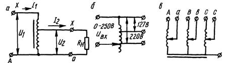
Rice.1 Autotransformer device: a — step-down, b — circuit, c — three-phase
In an autotransformer, the voltage and current in the primary and secondary windings are related by the same ratios as in transformers, i.e. U2 / U1 = W2 / W1 = K, where U2 and U1 are the voltages in the secondary and primary windings; W2 and W1 — the number of turns in the respective windings; K is the transformation coefficient.
 The resulting power in the secondary winding (autotransformer power) will be P2 = Pat = U2I2.
In the case of a step-down transformer, I = I2 — I1 or I2 = I + I1.
Therefore, Rat = U2I2 = U2 (I + I1) = U2I + U2I1.
It follows that Rath consists of two terms: power Pt = U2I delivered to the secondary winding due to the transformer (magnetic) connection between the two circuits; power Pe = U2I1 transmitted from the primary winding to the secondary due to the simultaneous electrical connection between the windings.
 The power Pt is the power for which the autotransformer must be calculated:
to lower Pt = Rat (1 — K),
for increasing Pt = Rat (1 — 1 / K).
Core cross-sectional area S = 1.2√PT.
The number of windings at 1 V voltage, W0 = 45000 / BH, where H is the magnetic induction of the core; B — magnetizing force.
The number of turns of each of the windings W1 = WU1; 2 = WU2.
The winding of the autotransformer during continuous operation should not be heated above 65 degrees C. To avoid this, the current density in the wire should not exceed 2 ... 2.2 A / 1 mm² of its cross section.
The diameter of the wire is calculated by the formula d = 0.8√Az, where d is the diameter of the winding wire, mm; I is the current in the corresponding coil, A.
The current consumed by the autotransformer from the network, I1 = Rat / U1, load current I2 = Rat / U2.