Measurement of DC and AC single-phase current
 From the expression for direct current power P = IU, it can be seen that it can be measured using an ammeter and a voltmeter by an indirect method. However, in this case, it is necessary to carry out simultaneous readings from two instruments and calculations, which complicate the measurements and reduce its accuracy.
To measure power in DC and single phase alternating current they use devices called wattmeters that use electrodynamic and ferrodynamic measuring mechanisms.
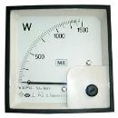
Electrodynamic wattmeters are produced in the form of portable devices with high accuracy classes (0.1 — 0.5) and are used for accurate measurements of AC and DC power at industrial and elevated frequencies (up to 5000 Hz). Ferrodynamic wattmeters are more often found in the form of panel instruments with a relatively low accuracy class (1.5 — 2.5).
Such wattmeters are mainly used in industrial frequency alternating current. At direct current, they have a significant error due to the hysteresis of the cores.
To measure power at high frequencies, thermoelectric and electronic wattmeters are used, which are a magnetoelectric measuring mechanism equipped with an active power to direct current converter. The power converter performs the operation of multiplication ui = p and obtaining a signal at the output that depends on the product ui, that is, the power.
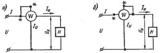
In fig. 1, and the possibility of using an electrodynamic measuring mechanism to construct a wattmeter and measure power is shown.
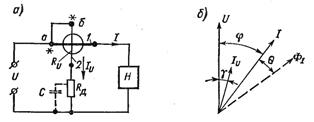
Rice. 1. Wattmeter switching scheme (a) and vector diagram (b)
The stationary coil 1, connected in series with the load circuit, is called the series circuit of the wattmeter, the moving coil 2 (with an additional resistor), connected in parallel with the load, the parallel circuit.
For a constant wattmeter:
Consider the operation of an electrodynamic wattmeter on alternating current. Vector diagram fig. 1, b is constructed for the inductive nature of the load. Current vector Iu the parallel circuit lags behind the vector U by the angle γ due to some inductance of the moving coil.
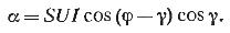
It follows from this expression that the wattmeter correctly measures power only in two cases: when γ = 0 and γ = φ.
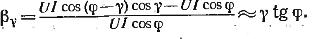
A state γ = 0 can be achieved by creating voltage resonance in a parallel circuit, for example, by including a capacitor C of the corresponding capacitance, as shown by a dotted line in fig. 1, a. However, the voltage resonance will only be at a certain specific frequency. Condition for change of frequency γ = 0 is violated. When γ is not equal to 0, the wattmeter measures the power with an error βy, which is called the angular error.
At a small value of the angle γ (γ usually no more than 40 — 50 '), relative error
At angles φclose to 90 °, the angular error can reach large values.
The second, specific error of wattmeters is the error caused by the power consumption of its coils.
When measuring the power consumed by the load, two wattmeter switching circuits, differing in the inclusion of its parallel circuit (Fig. 2).
Rice. 2. Schemes for turning on the parallel winding of the wattmeter
If we do not take into account the phase shifts between the currents and voltages in the coils and consider the load H to be purely active, the errors βa) and β(b), due to the energy consumption of the wattmeter windings, for the circuits of fig. 2, a and b:
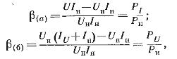
where P.i and P.ti — respectively, the power consumed by the series and parallel circuits of the wattmeter.
From the formulas for βa) and β(b), it can be seen that errors can have appreciable values only when measuring power in low-power circuits, i.e. when Pi and P.ti commensurate with Rn.
If you change the sign of only one of the currents, the direction of deflection of the moving part of the wattmeter will change.
The wattmeter has two pairs of clamps (series and parallel circuits) and depending on their inclusion in the circuit, the direction of deflection of the pointer can be different. For the correct connection of the wattmeter, one of each pair of clamps is marked with a «*» (asterisk) and is called the «generator clamp».