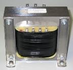
Rectifier transformers
 In the circuit of the secondary windings of the transformers working on the rectifier installations, electric valves are connected, passing current in only one direction.
The operation of the transformer together with valve devices has its own characteristics:
1) the shape of the currents in the coils is non-sinusoidal,
2) in some rectification circuits, additional magnetization of the transformer core is carried out,
The appearance of higher harmonic currents in the curves occurs due to the following reasons:
1) valves included in the circuits of individual phases of the current of the secondary winding pass through only part of the period,
2) on the DC side of the converter, a smoothing choke with a significant inductance is usually included, in which the currents in the transformer windings have a shape close to rectangular.
 Higher harmonic currents cause additional losses in the windings and the magnetic circuit, therefore, in order to avoid overheating, they are forced to increase the overall dimensions and weight of the transformers in the rectifier circuits.
Additional magnetization of the transformer core is accomplished using half-wave rectification circuits.
In a single-phase half-wave rectifier circuit, the secondary current i2 is pulsating and has two components: a constant iq and a variable iband:
i2 = id + ipay
The DC component depends on the values of the rectified voltage Ud and load Zn.
Its effective value is determined by the expression:
Azd = √2Ud / πZn
Thus, the equation for the balance of the magnetomotive forces can be written in the following form:
i1W1 + iW2 + iW2 = i0W1
 In this expression, all components are variable quantities, except for iW2. This means that the latter cannot be transformed into the primary winding (the DC transformer does not work) and therefore cannot be balanced. Therefore, MDS idW2 creates an additional magnetic flux in the magnetic circuit, which is called forced magnetization flux... In order not to cause this flux to cause unacceptable saturation of the magnetic system, the size of the magnetic circuit is increased.
To compensate for forced magnetization in half-wave rectifier circuits, a Y/Zn coil connection scheme or compensating coils is used. The principle of forced magnetization flux compensation is similar to zero sequence flux compensation.
 It should be noted that in full-wave rectification circuits, when the current in the secondary circuit is created during both half-cycles, there is no additional forced magnetizing flux.
Therefore, due to the presence of higher harmonic currents and forced magnetizing flux, transformers in rectifier installations are larger than conventional transformers and therefore more expensive. Due to the fact that the primary and secondary currents of the transformer are not the same, the calculated power of the windings is also not the same. Therefore, the concept is introduced typical power Stip:
Stip = (S1n + S2n) / 2,
where S1n and S2n — nominal power of the primary and secondary windings, kV -A.
Since the output power Pd: Pd = UdAzd is not equal to the typical one, the use of the transformer is also characterized by the typical power factor Ktyp:
Ktyp = Styp / Rd.
The typical power of the transformer is always higher than its power Az2 > Azq and U2 > Ud
Behavior U2/ Ud = Kthe so-called correction factor. When choosing a correction scheme, it is necessary to know the values \u200b\u200bof Ki and Ktyp. The table shows their values for the most common correction schemes.
Rectifier circuits Ku Ktyp Single-phase half-wave 2.22 3.09 Single-phase full-wave bridge 1.11 1.23 Single-phase full-wave with zero terminal 1.11 1.48 Three-phase half-wave 0.855 1.345 Three-phase full-wave 0.427 1.05