Calculation of three-phase circuits
 Chain three-phase alternating current consists of a three-phase power supply, a three-phase consumer and the communication line wires between them.
A symmetrical three-phase supply can be represented as three single-phase supplies operating at the same frequency with the same voltage and with a phase angle in time of 120 °. These sources can be star or delta connected.
When connected in a star, the conditional beginning of the phases is used to connect three linear conductors A, B, C, and the ends of the phases are united at one point, called the neutral point of the power source (three-phase generator or transformer). A neutral wire N can be connected to this point. The star connection diagram of the power source is shown in Figure 1, a.
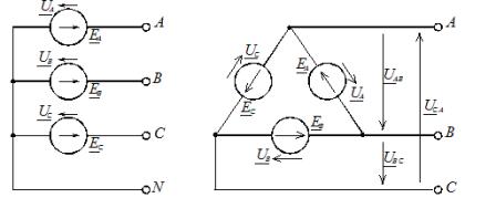
Rice. 1. Connection diagrams of the power supply phases: a — star; b — triangle
The voltage between line and neutral conductor is called phase and between line conductors is called line (for more details see here – Line and phase voltage).
V integrated form the entries of the expressions for the phase voltages are:

The corresponding line voltages when star connected:
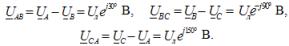
Here Uf is the phase voltage modulus of the power source and Ul is the line voltage modulus. In a symmetrical three-phase system, when the source phases are star-connected, there is a relationship between these voltages:

When the phases are connected with a triangle, the phase power supplies are connected in series in a closed loop (Figure 1, b).
Three linear wires A, B, C are brought out from the points of combining the sources with each other, going to the load. From Figure 1, b, it can be seen that the outputs of the phase sources are connected to linear wires, and therefore, when the phases of the source are connected by a triangle, the phase voltages are equal to linear. In this case, there is no neutral wire.
A load can be connected to a three-phase supply. In terms of size and nature, a three-phase load can be symmetrical and asymmetrical.
In the case of a symmetrical load, the complex resistances of the three phases are the same, and if these resistances are different, then the load is unbalanced. The load phases can be connected to each other by star or delta (Figure 2), regardless of the source connection scheme.
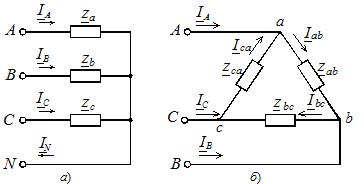
Rice. 2. Load phase connection diagrams
The star connection can be with or without a neutral wire (see Figure 2, a). The absence of a neutral wire eliminates the rigid connection of the load voltage to the supply voltage, and in the case of an asymmetric phase load, these voltages are not equal to each other.To distinguish them, we agreed to use capital letters in the letter designation indices of the supply voltages and currents, and lower case letters in the load-specific parameters.
The algorithm for analyzing a three-phase circuit depends on the load connection scheme, the initial parameters and the purpose of the calculation.
The two-node method is used to determine the phase voltages with an unbalanced star-connected load without a neutral conductor. According to this method, the calculation begins with the determination of the voltage UN between the neutral points of the supply and the load, called the neutral deviation voltage:
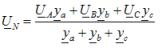
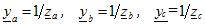
where ya, yb, yc — permissible values of the corresponding load phases in complex form
The voltages across the phases of an unbalanced load are found from the expressions:

In the special case of load unbalance, when, in the absence of a neutral conductor, a short circuit occurs in one of the load phases, the neutral bias voltage is equal to the phase voltage of the supply of the phase in which the short circuit occurred.
The voltage on the closed phase of the load is zero, and on the other two it is numerically equal to the line voltage. Suppose, for example, that a short circuit occurs in phase B. The neutral bias voltage for this case is UN = UB. Then the phase voltages on the load:

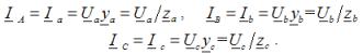
Phase currents in the load, they are also line conductor currents for any type of load:
In the tasks when calculating three-phase circuits, three options for connecting three-phase consumers with a star are considered: connection to a neutral wire in the presence of consumers in three phases, connection to a neutral wire in the absence of consumers in one of the phases, and connection without a neutral wire with a short compound in one of the load phases...
In the first and second versions, the corresponding phase voltages of the supply are located on the load phases and the phase currents in the load are determined by the above formulas.
In the third version, the voltage of the load phases is not equal to the phase voltage of the supply and is determined using the dependencies
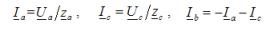
The currents in two unshorted phases are determined according to Ohm's law, as a fraction of the division of the phase voltage by the impedance of the respective phase. The short-circuit current is determined using an equation based on Kirchhoff's first lawcompiled for the neutral point of the load.
For the above example of a phase B short circuit:
For each type of load, the three-phase active and reactive powers are equal to the sum of the active and reactive powers of the individual phases, respectively. To determine these phase powers, you can use the expression
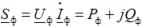
where Uf,Azf, is the complex of the voltage and the complex of coupled currents in the load phase; Pf, Qf — active and reactive power in the load phase.
Three-phase active power: P = Pa + Pb + Pc
Three-phase reactive power: Q = Qa + Qb + Vc
Three-phase apparent power:
When consumers are connected by a triangle, the circuit takes the form shown in Figure 2, b. In this mode, the phase connection of the balanced power supply is irrelevant.
Voltages between the power supply lines are detected on the load phases. The phase currents in the load are determined using Ohm's law for a section of a circuitAzf = Uf /zf, where Uf — phase voltage in the load (corresponding to the mains voltage of the power source); zf is the total resistance of the corresponding phase of the load.
Currents in linear conductors are determined by phase currents based on Kirchhoff's first law for each node (points a, b, c) of the circuit shown in Figure 2, b:
