Electric shaft and its application in the electric drive of metal cutting machines
 The article discusses the device, the principle of operation and examples of the use of electric systems for synchronous rotation (electric shaft) in metal-cutting machines and installations.
Assume that two shafts that are not mechanically connected to each other are to rotate at the same speeds without turning relative to each other. To ensure such synchronous and in-phase rotation with motors D1 and D2, which rotate shafts A and II, respectively (Fig. 1), connect auxiliary asynchronous machines A1 and A2 with phase rotors. The rotor windings of these machines are connected against each other.
If the rotational speeds of the two machines and the positions of their rotors are the same, then the electromotive forces induced in the windings of the rotors of machines A1 and A2 are equal and directed towards each other (Fig. 2, a), and the current does not flow in the rotor circuit.
Assume that the direction of rotation of the field of the auxiliary machines coincides with the direction of rotation of their rotors.As the rotation of machine A2 slows down, its rotor will lag behind that of A1, resulting in e. etc. c. Ep2 induced in the rotor winding will shift in phase to the advance (Fig. 2, b), and in the rotor circuit of machines A1 and A2 under the action of the vector sum of e. etc. with E, the equalizing current Az appears.
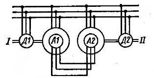
Rice. 1. Scheme of synchronous communication
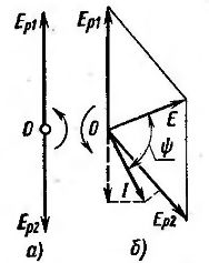
Rice. 2. Vector diagrams of the synchronous communication system
The current vector I will lag the vector e. etc. with E in the angle φ... Current vector projection Az onto the vector e, etc. v. Ep2 coincides with this vector in direction. The projection of the current vector onto the vector e. etc. pp. Ep1 is aimed at him. It follows that machine A2 will operate in engine mode and machine A1 in generator mode. In this case, the shaft of machine A2 will be accelerated and the shaft of machine A1 will be decelerated. In this way, the machines will develop torques that restore the synchronous rotation of the shafts. I and II and the previous coordinated position in space of the rotors of machines A1 and A2. The rotors of these machines can rotate both in the direction of rotation of the field and in the opposite direction.
This system is called an electric synchronous rotation system… It is also called an electric shaft… The synchronous rotation system can replace, for example, lead screws in screw cutting lathes.
Since the feed circuits of metal cutting machines, compared to the circuits of the main motion, usually consume low power, a simpler scheme of synchronous rotation can be used to synchronize the main motion with the feed (Fig. 3).In this case, a constant mismatch between the positions of the rotors of machines A1 and A2 is inevitable, without which there would be no current in the rotor circuit of machine A2 and it would not be able to overcome the moment of the resistive forces of the supply circuit. Since the A2 machine receives power from the stator and rotor, this electric shaft system requires a six-wire connection to the motor, installed in many cases on a moving machine block, usually shown in the dotted line figure.
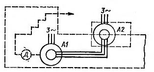
Rice. 3. Synchronous communication systems of a heavy screw lathe
Within the angular deviation, which does not exceed 90 °, the electrical synchronizing moment increases. In order to ensure a significant synchronizing torque, synchronous communication machines at all possible angular frequencies of rotation must operate with large slips (not less than 0.3 — 0.5). Therefore, these machines must be large enough to avoid unacceptable heating.
The power of the machines is further increased in an attempt to eliminate the influence of load fluctuations and frictional forces. Mechanical transmissions are also used, which reduce the frequency of rotation of the machine shafts and, accordingly, the magnitude of the angular error reduced to the machine shaft. Before starting the operation of the electric shaft, the asynchronous machines A1 and A2 are connected to a single-phase power supply. In this case, the rotor of machine A2 takes its initial position, which corresponds to the position of the rotor of machine A1.
Synchronous rotation systems rationally used for heavy metal cutting machines, since the production of long lead screws is associated with significant difficulties.In addition, as the length of the screws or shafts increases, due to their twisting, the accuracy of the coordination of the mutual arrangement of the machine parts decreases. In an electric shaft system, the distance between the shafts cannot affect the accuracy of the operation.
When using an electric shaft, the mechanical connections of the calipers to the spindle are eliminated and the kinematic diagram is greatly simplified. A significant disadvantage of electric shaft systems in heavy metal cutting machines is the possibility of damage to an expensive part during a power failure, as misalignment immediately occurs. In some cases, in such an accident, damage to the workpiece can be prevented by rapid automatic retraction of the tool.
A scheme with two identical asynchronous motors with phase rotors is of interest for mechanical engineering (Fig. 4). Since the circuit of both rotors is closed to the rheostat R, when the motors are connected to the AC mains, both rotors start to rotate.
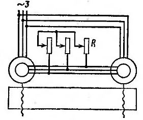
Rice. 4. Scheme of synchronous communication with a rotary rheostat
In addition to the currents flowing in the rotor and rheostat windings, an equalizing current flows in the rotor circuit of both machines. The presence of this current causes a synchronizing torque to appear, as a result of which the machines rotate synchronously. This system can be used to raise and lower the cross arms of large planers, routers and carousels.
Thanks to the electric shaft system, the problem of coordinated movement of conveyors that are part of a production complex is solved.The most practical application in this case is obtained from the variant of synchronous rotation of motors with a common frequency converter.
In addition to the electric shaft systems for machine building considered, other AC machine systems have been developed and used, including single-phase systems and systems with synchronous motors of special construction.