Electrical measurements of non-electrical quantities
 The measurement of various non-electric quantities (displacements, forces, temperatures, etc.) by electrical methods is carried out with the help of devices and instruments that convert non-electric quantities into electrically dependent quantities, which are measured by electrical measuring instruments with balances calibrated in units of measured non-electric quantities.
Converters of non-electric quantities into electrical or sensors divided into parametric based on the change of any electrical or magnetic parameter (resistance, inductance, capacitance, magnetic permeability, etc.) under the influence of the measured quantity, and a generator in which the measured non-electric quantity is transformed into e. etc. (induction, thermoelectric, photoelectric, piezoelectric and others). Parametric converters require an external source of electrical power, and generator units themselves are power sources.
The same transducer can be used to measure different non-electrical quantities conversely, the measurement of any non-electrical quantities can be done using different types of transducers.
In addition to converters and electrical measuring devices, installations for measuring non-electric quantities have intermediate connections — stabilizers, rectifiers, amplifiers, measuring bridges, etc.
To measure linear displacements, use inductive transducers — electromagnetic devices in which the parameters of the electric and magnetic circuit change when moving the ferromagnetic magnetic circuit or armature connected to the moving part.
To convert significant displacements into an electrical value, a transducer with a movable ferromagnetic translationally moving magi-conductor is used (Fig. 1, a). Since the position of the magnetic circuit determines the inductance of the converter (Fig. 1, b) and, therefore, its impedance, then with a stabilized voltage of the source of electrical energy with an alternating voltage of constant frequency feeding the circuit of a converter, according to the current it is possible to the movement of the part mechanically connected to the magnetic circuit is estimated ... The scale of the instrument is graduated in the appropriate units of measurement, for example in millimeters (mm).
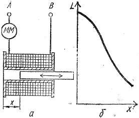
Rice. 1. Inductive converter with a movable ferromagnetic magnetic circuit: a — diagram of the device, b — graph of the dependence of the inductance of the converter on the position of its magnetic circuit.
To convert small displacements into a value convenient for electrical measurement, transducers with a variable air gap are used in the form of a horseshoe with a coil and an armature (Fig. 2, a), which is firmly connected to the moving part. Each movement of the armature leads to a change in the current / in the coil (Fig. 2, b), which allows the scale of the electrical measuring device to be calibrated in units of measurement, for example, in micrometers (μm), at a constant alternating voltage with a stable frequency.
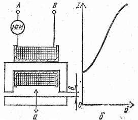
Rice. 2. Inductive converter with a variable air gap: a — diagram of the device, b — graph of the dependence of the current of the coil of the converter on the air gap in the magnetic system.
Differential inductive converters with two identical magnetic systems and one common armature, located symmetrically to the two magnetic circuits with an air gap of the same length (Fig. 3), in which the linear movement of the armature from its middle position changes both air gaps equally, but with various signs that upset the balance of the pre-balanced four-coil AC bridge. This makes it possible to estimate the movement of the armature according to the current of the measuring diagonal of the bridge, if it receives power at a stabilized alternating voltage of constant frequency.
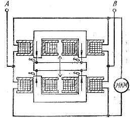
Rice. 3. Scheme of the device of the differential inductive converter.
Use to measure mechanical forces, stresses and elastic deformations occurring in parts and assemblies of various structures wire - tension transducers, which, being deformed, together with the parts under study, change their electrical resistance.Typically, the resistance of a strain gauge is several hundred ohms, and the relative change in its resistance is a tenth of a percent and depends on the deformation, which in the elastic limits is directly proportional to the applied forces and the resulting mechanical stresses.
The strain gauges are made in the form of a high-resistance zigzag wire (constantan, nichrome, manganin) with a diameter of 0.02-0.04 mm or from a specially processed copper foil with a thickness of 0.1-0.15 mm, which are sealed with bakelite varnish between two thin layers of paper and subjected to heat treatment (Fig. 4, a).
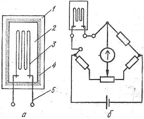
Rice. 4. Tenometer: a — diagram of the device: 1 — deformable part, 2 — thin paper, 3 — wire, 4 — glue, 5 — terminals, b — circuit for connecting an unbalanced resistor bridge to the arm.
The fabricated strain gauge is glued to a well-cleaned deformable part with a very thin layer of insulating glue so that the direction of the expected deformation of the part coincides with the direction of the long sides of the wire loops. When the body is deformed, the glued strain gauge perceives the same deformation, which changes its electrical resistance due to a change in the dimensions of the sensing wire, as well as the structure of its material, which affects the specific resistance of the wire.
Since the relative change in the resistance of the strain gauge is directly proportional to the linear deformation of the body under study and, accordingly, to the mechanical stresses of the internal elastic forces, then, using the readings of the galvanometer on the measuring diagonal of the pre-balanced resistor bridge, one of the arms of which is the strain gauge, can to estimate the value of the measured mechanical quantities (Fig. 4, b).
The use of an unbalanced bridge of resistors requires stabilization of the voltage of the power source or the use of a magnetoelectric ratio as an electrical measuring device, on the readings of which a voltage change within ± 20% of the nominal voltage indicated on the scale of the device has no significant effect.
Use thermosensitive and thermoelectric transducers to measure the temperature of various media... Thermosensitive transducers include metal and semiconductor thermistors, the resistance of which largely depends on temperature (Fig. 5, a).
The most widespread are platinum thermistors for measuring temperatures in the range from -260 to +1100 ° C and copper thermistors for the temperature range from -200 to +200 ° C, as well as semiconductor thermistors with a negative coefficient of electrical resistance — thermistors, characterized by high sensitivity and small size compared to metal thermistors, for measuring temperatures from -60 to +120 ° C.
To protect the temperature-sensitive transducers from damage, they are placed in a thin-walled steel tube with a sealed bottom and a device for connecting wires to the wires of an unbalanced resistor bridge (Fig. 5, b), which makes it possible to estimate the measured temperature along the current of the measuring diagonal. The scale of the magnetoelectric ratio used as a meter is graduated in degrees Celsius (°C).
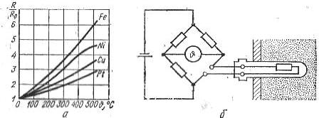
Rice. 5. Thermistors: a — graphs of the dependence of the change in the relative resistance of metals on temperature, b — a circuit for connecting thermistors to the arm of an unbalanced resistor bridge.
Thermoelectric temperature transducers — thermocouples, generation of small e., etc. c. under the influence of heating the compound of two different metals, they are placed in a protective plastic, metal or porcelain shell in the area of the measured temperatures (Fig. 6, a, b).
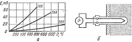
Rice. 6. Thermocouples: a — graphs of the dependence of d, etc. p. for the temperature of thermocouples: TEP-platinum-rhodium-platinum, TXA-chromel-alumel, THK-chromel-copel, b-assembly diagram for measuring temperature using a thermocouple.
The free ends of the thermocouple are connected by homogeneous wires to a magnetoelectric millivoltmeter, the scale of which is graduated in degrees Celsius. The most widely used thermocouples are: platinum-rhodium — platinum for measuring temperatures up to 1300 ° C and for a short time up to 1600 ° C, chromel-alumel for temperatures corresponding to the indicated regimes — 1000 ° C and 1300 ° C and chromel- bastard, designed for long-term measurement of temperatures up to 600 ° C and short-term - up to 800 ° C.
Electrical methods for measuring various non-electric quantities. They are widely used in practice, as they provide high measurement accuracy, differ in a wide range of measured values, allow measurements and their registration at a considerable distance from the location of the controlled object, and also give possibility to perform measurements in hard-to-reach places.