Sources of electrical signals
 The potential difference between two different points is called an electric voltage, which for brevity is simply called "voltage", since the theory of electric circuits is primarily concerned with electrical phenomena or processes. Therefore, if two regions whose potentials differ from each other are somehow created, then a voltage U = φ1 — φ2 will appear between them, where φ1 and φ2 are the potentials of the regions of the device in which, due to the consumption of little energy electric potentials with unequal values are formed...
For example, a dry cell contains various chemicals — coal, zinc, agglomerate, and others. As a result of chemical reactions, energy (in this case chemical) is expended, but instead, areas with different numbers of electrons appear in the element, which causes unequal potentials in those parts of the element where the carbon rod and zinc cup are located.
Therefore, there is a voltage between the wires from the carbon rod and the zinc cup. This voltage across the open terminals of the source is called electromotive force (abbreviated EMF).
Thus, the EMF is also a voltage, but under quite certain conditions. Electromotive force is measured in the same units as voltage, namely volts (V) or fractional units - millivolts (mV), microvolts (μV), with 1 mV = 10-3 V and 1 μV = 10-6 V.
The term «EMF», which has developed historically, is strictly speaking inaccurate, since the EMF has the dimension of voltage, not force at all, which is why it has recently been abandoned, replacing the terms «internal voltage» (i.e., the voltage, excited inside the source) or «reference voltage». Since the term «EMF» is used in many books and GOST has not been canceled, we will use it in this article.
Therefore, the source electromotive force (EMF) is the potential difference generated inside the source as a result of the consumption of some type of energy.
Sometimes it is said that the EMF at the source is formed by external forces, which are understood as influences of a non-electrical nature. So, in generators installed in industrial power plants, EMF is formed due to the consumption of mechanical energy, for example, the energy of falling water, burning fuel, etc. Currently, solar batteries are becoming more common, in which light energy is converted into electrical energy and etc.
 In communication technology, radio electronics and other branches of technology, electrical voltages are obtained from special electronic devices called signal generators, in which the energy of the industrial electrical network is converted into different voltages taken from the output terminals.In this way, signal generators consume electrical energy from the industrial network and also produce voltages of an electrical type, but with completely different parameters, which cannot be obtained directly from the network.
The most important characteristic of any voltage is its dependence on time. In general, generators produce voltages whose values change with time. This means that at any moment the voltage at the output terminals of the generator is different. Such voltages are called variables, in contrast to constants, whose values remain unchanged with time.
It must be remembered that it is fundamentally impossible to transmit any information (speech, music, television images, digital data, etc.) with constant voltages, and since the communication technique is designed specifically for the transmission of information, the main attention will be turned to account for time-varying signals.
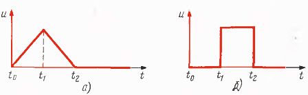
Voltages at any instant of time are called instantaneous... Instantaneous voltage values are usually time-dependent variables and are denoted by lowercase (lower case) and (t) or, for short, — and. The summation of instantaneous values forms a waveform. For example, if in the interval from t = 0 to t = t1 the voltages increase in proportion to time, and in the interval from t = t1 to t = t2 they decrease according to the same law, then such signals have a triangular shape.
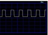
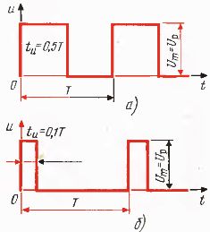
They are very important in communication technologies square wave signals… For such signals, the voltage in the interval from t0 to t1 is equal to zero, at the moment t1 sharply rises to the maximum value, in the interval from t1 to t2 it remains unchanged, at the moment t2 sharply decreases to zero, etc.
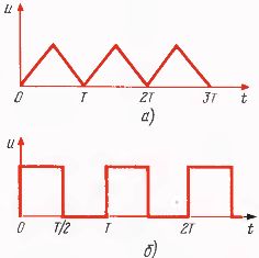
Electrical signals are divided into periodic and non-periodic. Periodic signals are called signals whose instantaneous values repeat after the same time, called period T. Non-periodic signals appear only once and do not repeat again. The laws governing periodic and non-periodic signals are very different.
Rice. 1
Rice. 2
Rice. 3
Many of them, being completely correct for periodic signals, turn out to be completely incorrect for non-periodic ones and vice versa. The study of non-periodic signals requires a much more complex mathematical apparatus than for the study of periodic ones.
Rectangular signals with pauses between pulses or, as they are called, "bursts" (from the concept of "sending signals") are very important. Such signals are characterized by a duty cycle, i.e. the ratio of the period time T to the sending time ti:

For example, if the pause time is equal to the pulse time, that is, the sending occurs within half the period, then the duty cycle
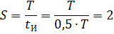
and if the sending time is one-tenth of the period, then
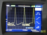
To visually observe the waveform of the voltage, measuring instruments are called oscilloscopes... On the screen of the oscilloscope, the electron beam traces a curve of the voltage that is applied to the input terminals of the oscilloscope.
When the oscilloscope is normally turned on, the curves on its screen are obtained as a function of time, that is, beam tracing images similar to those shown in fig. 1, a — 2, b.If in one electron beam tube there are devices that create two beams and thus allow two images to be observed at once, then such oscilloscopes are called double-beam oscilloscopes.
Dual-beam oscilloscopes have two pairs of input terminals, called channel 1 and channel 2 inputs. Dual-beam oscilloscopes are much more advanced than single-beam oscilloscopes: they can be used to visually compare the processes in two different devices, at the input and output terminals of one device, as well as to perform a number of very interesting experiments.
Rice. 4
The oscilloscope is the most modern measuring device used in electronic engineering, with its help you can determine the shape of signals, measure voltages, frequencies, phase shifts, observe spectra, compare processes in different circuits, and also perform a number of measurements and research, which will be discussed in the following sections.
The difference between the largest and the smallest instantaneous value is called the swing voltage Up (a capital letter indicates that a constant in the time value is being described, and the subscript «p» stands for the word «range». The notation Ue can also be used). thus, on the screen of the oscilloscope, the observer sees the shape of the investigated voltage and its range.
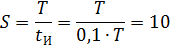
For example, in FIG. 4a shows a sinusoidal voltage curve, in FIG. 4, b — half wave, in fig. 4, c — full wave, in fig. 4, d — complex form.
If the curve is symmetrical about the horizontal axis, as in fig. 3, a, then half of the range is called the maximum value and is denoted by Um.If the curve is one-sided, that is, all instantaneous values have the same sign, for example, positive, then the swing is equal to the maximum value, in this case Um = up (see Fig. 3, a, 3, b, 4. b, 4, c). Thus, in communication engineering, the main characteristics of voltages are: period, shape, range; in any experiments, calculations, studies, one must first of all have an idea of these values.