Command devices and programmable loop control devices
 The cyclic nature of the production processes of many mechanisms led to the emergence of a special class of control devices that ensure the execution of the work program of the executive devices in a given sequence. Such devices are called command devices or command controllers.
The commander is a mechanical device that periodically acts on electrically sensitive elements that generate control signals. The main part of such a device is a shaft or drum that receives motion from the mechanism of a machine tool or an electric motor. In the first case, the control is carried out in the function of moving the machine tool bodies, and in the second - in the function of time.
An example is an adjustable cam controller, series KA21, the schematic diagram of which is shown in fig. 1. Microswitches 5 are used as switching elements in the controller, fixed on the insulating rail 2 with two screws: 3 and 6.Screw 3 is an adjusting screw, it can be used to change the position of the microswitch relative to the roller pusher 4.
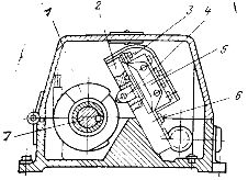
Rice. 1. KA21 series adjustable controller.
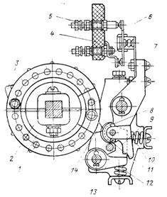
Rice. 2. KA4000 Series Cam Controller.
Shaft 7 with cams 1, which are disks with two movable sectors, serves as a distribution element of the controller. By changing the relative position of the sectors and turning the cam relative to the shaft, it is possible to change the duration of the on position of the microswitch and the moment of operation.
The commander is placed in a sealed housing and in some cases is equipped with a gearbox that changes the length of the control cycle. From 3 to 12 cams and the corresponding number of microswitches are mounted on the controller shaft.
KL21 series control devices designed for switching AC 380 V, 4 A and DC 220 V, 2.5 A. Switching life is 1.6 million cycles, mechanical endurance reaches 10 million cycles.
For software switching of high-power circuits, use command devices of the KA4000 series with instantaneous disconnection of contacts, the construction of which is shown in fig. 2. Shaft 1 of the controller has a square cross-section, which allows you to fix control washers 2, consisting of two halves. The washers are provided with holes for fixing the cams 3 and 14, which are mounted on both sides of the washer. The cam housing has an elongated groove that allows it to slide relative to the mounting hole. The shaft with pulleys and cams forms a camshaft drum, which determines the program of the command device.
The contact system of the bridge-type controller consists of fixed contacts 5 mounted on an insulating bus 4 and a movable contact part 6 connected to the lever 7. When the drum rotates, the switching cam 14 flows on the contact roller 11 and turns the lever 7, closing the contact system and pressing the return spring 10. At the same time, the lock 13 of the stop lever 9 under the action of the spring 12 exceeds the protrusion of the lever 7, fixing the contact system in the closed position after the cam 14 turns and stops contacting the roller 11.
The contact system is turned off by the second cam 3, which moves on the roller 8, turns the disconnecting lever 9 and releases the lever 7, which, under the action of the return spring 10, immediately opens the contacts of the controller. This allows switching of power circuits while the drum is slowly rotating.
For more complex duty cycles, up to three on and three off cams can be fitted on one pulley. The command devices of this series have a built-in spiral or worm gear with a transmission ratio from 1: 1 to 1:36; sometimes they are equipped with an electric drive. The number of included circuits is from 2 to 6. With a larger number of circuits, two drums are installed in the controller. The maximum speed of rotation of the drum is up to 60 rpm. Electrical endurance of the commander 0.2 million cycles, mechanical endurance 0.25 million cycles.
As a command device, they often use a step finder, the device of which is shown in fig. 3. The contact system of the stepped seeker is a set of fixed contacts (lamellas) 1 located in a circle. A movable brush 2 slides along the lamellae, which are fixed along axis 3.The brush is connected to the external circuit by means of a movable current conductor 10. The gradual movement of the brush is carried out by a ratchet mechanism consisting of a ratchet wheel 5, a working dog 6 and a locking dog 9. The ratchet mechanism has an electromagnetic drive 7. When a control is applied pulse to the electromagnet coil, the armature is attracted to the core and turns the ratchet wheel with one tooth. As a result, the brush moves from one lamella to another and makes a switch in the external circuit.
The stepper has several rows of blades and brushes mounted on one axis. This allows you to increase the number of switched circuits.
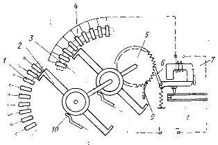
Rice. 3. Step search device.
The movable elements of the step finder can only move in one direction. Therefore, returning the brush to its original position is possible only after it has made a full rotation. If the number of strokes in the operating cycle of the command device is less than the number of lamellas, then accelerated movement of the brush to the initial position is possible. For this, a special row of lamellas 4 is used, in which all lamellas, except for the zero one, are electrically connected to each other. The reverse circuit is shown in Fig. 3 with dotted line. It is formed by lamellae 4, an electromagnetic coil and its auxiliary breaking contacts 8.
Each time the electromagnet is actuated, contacts 8 open and the return circuit is broken. Contacts 8 close again, etc. slat, the return circuit opens and brush movement stops. Step contacts are designed for low currents (up to 0.2 A). Stepper devices with thyristor switches are used to switch power circuits.
Non-contact control devices are designed on the same principle as contact ones. The control unit has a central shaft with disks on which control elements (cams, screens, optical covers, etc.) are mounted. The sensitive elements of the command device are installed on the periphery of the disks on the stationary body. Inductive, photoelectric, capacitive and other converters are used as the last ones. For example, on the basis of the contact controller KA21 (see Fig. 1), a non-contact controller of the KA51 type is produced.
Contactless switching is carried out by generator stroke switches, similar in design to switches of the BVK type, which are installed instead of microswitches 5. These switches are controlled by aluminum sectors fixed on a shaft 7 instead of cams 1.
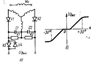
Rice 4. Schematic of a contactless command device based on selsyn
In fig. 4a shows a diagram of a made contactless command device based on selsin… The stator winding of selsyn Wc is connected to the mains. The voltage arising on the rotor windings is rectified by diodes V1 and V2, smoothed by capacitors C1 and C2 and fed to the load through resistors R1 and R2. The rotation of the selsyn rotor changes the EMF in its windings, resulting in a change in the rectified voltage. When the rotor is rotated in the opposite direction, the rectified voltage changes sign.
Such command devices are used in automated electric drive systems where it is necessary to give three commands: start in forward and reverse directions and stop. To more clearly fix the electric drive when braking, they create a dead zone of the controller.To do this, use the non-linearity of the current-voltage characteristics of diodes V3 and V4, which occurs at low currents. The graph of the change of the output voltage of the controller depending on the angle of rotation of the rotor a is shown in fig. 4, b.