Power supplies for DC electromagnets
 When direct current electromagnets are supplied directly from the direct current network, they are turned on by the control devices of the electric drive, and the protection of the electromagnetic circuits is carried out by common fuses or automatic switches of control circuits. When using forcing to reduce response time, the forcing time must be no more than:
— 0.3 s for electromagnets MP, VM12 and VM13,
— 0.6 s for the coils of electromagnets TKP, VM14 and KMPCh,
— 1.0 s for KMP 6 and VM 15 electromagnets.
In the event that direct current electromagnets of types MP 100-MP 300, VM 11-VM 13, KMP 2 are used for power supply from the alternating current network, typical half-wave rectifiers of type VSK 1 can be used, providing a corrected voltage of 220 V DC at power supply from a 380 V AC network or a rectified voltage of 110 V when supplied from a 220 V AC network due to the inclusion of a capacitor of a certain capacity in parallel with the coil of an electromagnet.
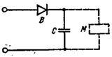
Rice. 1. Rectifier circuits VSK1.
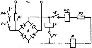
Rice. 2. Power supply circuit for DC electromagnets with force.
Rectifier circuit VSK 1 is shown in fig. 1. The silicon diode B is designed for a current of up to 3 A. The capacitor group C of the MBGO 2-600 type with a capacity of 6 to 14 μF provides output parameters that correspond to the conditions for supplying electromagnets.
The power supply of large brake electromagnets such as TKP 400 — TKP 800, VM 14, VM 15, KMP 4, KMP 6 can be carried out either from a common supply for auxiliary DC circuits or from an AC network according to the diagram shown in fig. 2. In this circuit B is a full wave rectifier assembled on silicon diodes V 2-25 of class 6-7, contactor K type KPD 111 with traction coil 220 V and arc extinguishing coil 10 A and RF relay type REV 816 with a coil of current 2.5, 5 or 10 A depending on the type of electromagnet.
The PT contact controls the process of engaging or disengaging the brake operated by the electric drive circuit. Resistors R1 and R2 are sized to provide the required load and boost mode. In particular, the resistor R1 in value and power is chosen equal to the resistance and power of the electromagnet coil, and the resistance of the resistor R2 limits the current in certain operating modes.
When powered according to the diagram in fig. 2 in the case of a nominal coil voltage of 110 V, the resistance of the resistor R1 is selected according to the reference tables, and the resistance, Ohm, and the power, W, of the resistor R2 are calculated by the formulas
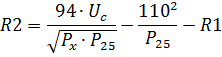
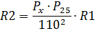
where Uc — alternating voltage in the network, P25- power of the electromagnetic coil in the operating mode PV = 25%, Px is the power of the electromagnet in a given mode.
Based on many years of practice, it has been established that no special protection of the circuits of MP 100 — MP 300 electromagnets is required when powered by VSK 1 rectifiers. When large electromagnets are powered by rectifier devices, including according to the diagram in fig. 2, it is necessary to protect the electromagnetic circuits by means of a circuit breaker type for a current that does not exceed 130% of the rated current of the electromagnet. In this case, one of the poles of the breaker is used in the circuit for zero blocking of the electric drive.