Crane protection equipment
General conditions for protection of electrical equipment of cranes from emergency situations
 According to the purpose, specifics of the work and design features, cranes are classified as equipment with increased danger, which is explained by the very process of operation of these mechanisms at sites and in premises where people and valuable equipment are located in the same place. time.
The general requirements for the safety of cranes and crane electrical equipment are formulated in accordance with the "Rules for the construction and safe operation of cranes" and "Rules for the construction of electrical installations".
All electrical equipment located in crane control cabins shall be supplied with earthed metal enclosures or shall be completely enclosed from the possibility of touching live parts. The control cabinet shall also contain a device that provides direct or remote shutdown of all power cable runs routed through the faucet, excluding input devices.
Exit to crane platforms where electrical equipment not protected by enclosures is located, current wires or trolleys trolleys, can only be carried out through doors and hatches that have a lock that cuts off the supply of all sources of electrical energy to the crane.
The section of main bogies, main pantographs and mains which remain live when the entire tap distribution is switched off. there must be reliable protection against accidental contact with them. This guard must have a lock with an individual key.
Repair and inspection of the live wires can only be carried out when the power supply to the main trolleys or the common input device located outside the crane is turned off. Chains of several cranes are powered by ordinary shop trolleys, then a repair area is provided where the trolleys can be switched off without interrupting the power supply to the other cranes.
Cranes are moving units and are subjected to vibrations and shocks during movement, therefore the possibility of damage to crane cables and wires is relatively higher than when they are stationary. In addition, on a number of cranes, the transfer of current to moving parts is carried out using flexible hose cables, the damage of which cannot be completely excluded. With this in mind, the first task of protection is to protect the electrical equipment of cranes from short circuit currents.
Currents k. H. in individual circuits within the tap will be smaller, smaller is the cross-section of the mounting wires of these circuits, and smaller are the sizes of the various current connections and current connectors. Maximum short-circuit currents in control circuits with a wire cross-section of 2.5 mm2 are 1200-2500 A.At the same time, to protect the circuits, it is possible to use fuses of the PR series for currents 6-20 A or any types of automatic switches AP 50, AK 63, etc. z., A, in electric motor circuits, roughly, can be determined by the formula
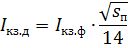
where Azkzyuf — short-circuit current in the supply phase, the line after 0.04 s; сn is the cross-section of the wire in the considered circuit, mm2.
Since the current k. F. should not destroy the switching device in this circuit until it is turned off, then when choosing devices and wire cross-sections, it is necessary to observe certain ratios that ensure the thermal resistance of the device. If we assume that the thermal resistance of most devices used in an electric crane drive is 10Azn for 1 s, then the ratio between the maximum permissible wire cross-section, mm2, and the rated current of the device should be as follows:

where Azn — nominal current of the device, A.
The last connection shows that at possible short-circuit currents. on a feeder with more than 8000 A it is unacceptable to install devices for 25 A due to thermal resistance. Devices for currents 63 A can only be used with a cable cross-section not greater than 6 mm2, and devices for current 100 A with a cable cross-section not greater than 16 mm2.
With possible short circuit currents. 12,000 A (limitation for taps) devices for currents of 63 A can only be used with cable cross-sections of no more than 4 mm2, i.e. at rated currents up to 30 A. Devices for a current of 100 A can be used with cable cross-sections of no more than 10 mm2, that is, at rated currents up to 60 A.Thus, for cranes driven by high-power power supplies, it is necessary either to install devices for currents not lower than 100-160 A, or to limit the cross-sections of wires to these devices in order to reduce the possible currents up to h.
Protection of the cable network of the crane from short circuit currents. is carried out using an instantaneous overcurrent relay and, if necessary, can be carried out by setting automatic devices.
Protection of wires from short circuit currents. complicated by the large power range of the mechanisms' electric motors within the same crane. In accordance with the rules for electrical installations, protective devices must be designed for a tripping current that does not exceed 450% of the continuous current of the protected circuit. The same rules for wires and cables operating with an intermittent load, the allowable heating current is determined by the expression

Where Azpv and Azn — nominal cable currents in intermittent and long-term modes of operation.
At duty cycle = 40% Azpv = 1.4 x Azn. Thus, the multiple of the protective setting to the permissible current of the wire (cable) should not exceed 450 / 1.4 = 320% of the current in a 40% duty cycle. The permissible loads of wires and cables in the tap at an ambient temperature of 45 ° C are given in the reference tables.
Electric crane drives have the following main types of protective devices:
• maximum protection for disconnecting the drive from the network in case of inadmissible currents in the protected circuit;
• zero protection to shut down the electric drive in case of interruption or interruption of power from the power source.One type of zero protection is zero blocking, which prevents the motor from starting on its own when power is restored on the supply line if the control is in the operating position
• maximum protection to prevent moving structures from moving beyond certain permissible limits.
 An important task of the protection system is to prevent inadmissible overloads for all types of electric drives of crane mechanisms associated with malfunctioning control circuits, jamming of mechanisms, open circuit of the brake, etc. This is the difference between the overload protection requirements of crane electric overload protection drives for electric drives with continuous operation...
Due to the uncertainty of the load on the crane mechanisms, the changing heating rates of the motors, their operation under conditions of frequent starts and brakes, it is not even possible to set the task of protecting electric drives from thermal overloads. The only condition for preventing thermal overloads of crane electrical equipment is its correct selection, taking into account all pre-calculated operating modes that are possible during operation.
In this way, overload protection is reduced to monitoring the inrush current during step-starting and protection against stalling of squirrel-cage motors or electric drives with current interruption. With a properly organized start of the electric drive with stepwise acceleration, the starting current should not exceed 220-240% of the current corresponding to the calculated value.
Taking into account the necessary margin for spreading both the inrush current and the maximum relay setting, the latter should be designed to operate at a current of about 250% of the rated, which may be equal to or less than the motor current in duty cycle = 40%.
According to the above, the overcurrent relay in the crane drive system is assigned two functions:
1. protection against short circuit currents. wires (cables) in each pole for direct current and in each phase for alternating current,
2. overload protection, for which it is enough to connect the relay to one of the poles or one of the phases.
In accordance with the rules, crane electric drives must have zero blocking, that is, in the event of a power failure, the electric actuator must be turned off, and its restart is possible only after the control element returns to its zero position. This requirement does not apply to floor buttons with self-adjusting buttons.
The presence of zero blocking excludes self-starting of electric crane drives, and also excludes multiple switching on when various protections are triggered.
Phase loss protection does not apply to valves. The analysis of the possible consequences of a phase loss outside the tap and an acceptable phase loss protection system showed that, on the one hand, there is currently no satisfactory technical solution for the use of a reliable, cheap and simple phase voltage control device, and on the other side, phase failure in and out of the tap is unlikely due to the fact that the use of fuses in the main circuit is not currently practiced.
New dynamic braking systems, replacing opposing braking systems, minimize the risk of load falling in case of phase loss.
Overload relay in crane drive
To protect the circuits of the electrical equipment of the crane from overloading, an electromagnetic instantaneous relay of the REO 401 type is used. These relays can be used in both AC and DC circuits. The relay has two designs. In fig. 1 shows a general view of the REO 401 relay.
The relay consists of two main blocks: an electromagnet 2 and an opening auxiliary contact 1. The solenoid coil 3 is located on the tube 4, in which the armature moves freely 5. The position of the armature in the tube is adjustable in height and determines the value of the actuation current on the relay. When the current in the coil rises above the operating current, the armature rises and opens the contacts through the pusher of the contact block.
In the second version, relay electromagnets in an amount of two to four parts are mounted on a common base, which also has a common bracket that transfers the forces of each individual electromagnetic armature to an auxiliary contact installed on the base. Thus, in this design, several electromagnets act on one auxiliary contact.
After switching off the current, the armature returns under its own weight. The relay has one NC auxiliary contact. The auxiliary contact is designed for AC switching up to 10 A at 380 V and or for DC switching 1 A at 220 V and L / R = 0.05
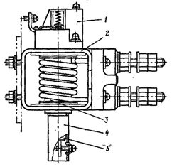
Rice. 1. General view of the REO 401 relay
Relay coils for currents above 40 A are made of bare copper. The terminals of these coils are located on a special insulating panel. Coils for currents up to 40 A are insulated. When choosing a relay for installation inoverall devices should be guided by the allowable coil load in the duty cycle = 40% and the operating range, taking into account the necessary trip settings.
REO 401 relays can perform their functions under the condition that the starting current of the electric drive is less than the current of the blocked electric motor when switched on at rated voltage, i.e. the protection of short-circuited electric motors and electric drives with current interruption using relay REO 401 is not possible. The protection of such electric motors must be carried out with thermal mode temperature-current relays TRT series.
TPT relays have five dimensions in the current range from 1.75 to 550 A. Relays of all types are enclosed in a plastic housing and differ in the shape of the reacting thermal element, the presence of an additional heater and the dimensions of the terminals. The fifth dimension relay is mounted on the current transformer. As a reactive thermal element of the relay, invastal bimetal is used, rationalized by current and additionally heated by a heater. The relay has one NC contact designed to switch AC 10 A, 380 V at Cos φ = 0.4 and DC 0.5 A, 220 V at L / R = 0.05.
The technical data of the TPT relay are given in the reference books. The timing characteristics of the TRT series relay are shown in Fig. 2. The relay does not operate at 110% of rated current in continuous operation. At a current of 135% of nominal, the relay picks up in 5–20 minutes. At 600% of the rated current, the relay picks up in 3 to 15 s. A relay regulator allows you to adjust the nominal setting current within ± 15%. The return of the relay contacts to the on state occurs 1-3 minutes after the power is turned off.
When choosing a relay, you should be guided by the conditions:
1) the average current of the protected circuit must not exceed the rated current of the heater;
2) with three starts in a row, the relay should not work;
3) the reaction time at the starting current must not be higher than the permissible standby time of the electric motor at current in this mode.
When using the operating time characteristic of the TPT relay, it should be borne in mind that the possible actual deviations of the operating current are about ± 20% of the setting current.
Protective panels
In accordance with the requirements, each crane must be equipped with a device designed to power the electric drives of the mechanisms and turn it off, in addition, the inclusion, i.e. the power supply can be done after unlocking the switching device using an individual brand key.
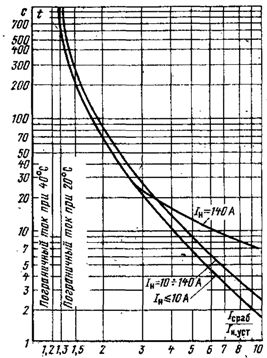
Rice. 2. Timing characteristics of the TRT series relay.
In turn, the key cannot be removed without performing the shutdown operation. This blocking makes it possible to ensure that the crane is put into operation only by a person who is authorized to operate the crane.
An individual key marking is used on all types of cranes with electric drive, except for construction tower cranes protective panel… For construction tower cranes, the specified key is used to lock out the main switch (or machine) in the tower crane power cabinet to which the flexible power cable is connected.
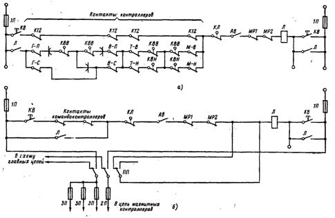
Rice. 3.Circuit diagram for control of protective panels: a — when controlling cam controllers; b — when managing magnetic controllers; 1P — ZP — fuses; KB — "return" button; KL — hatch contact; AB — emergency switch; L — linear contactor: MP1, MP2 — maximum relay contacts; KVV, KVN — limit switches; PP — check switch; K12 — zero contacts of the controllers.