Secondary circuit switching equipment
 A wide range of switching equipment is used in secondary circuits. Some of the more common devices are listed below.
Control switches, switches and buttons of different series and types have letter designations-PMO (small size switch for general industrial purposes), MK (small size switch), UP (universal switch), K (control buttons for closing and opening the contacts of the control circuits, signaling and protection) etc. Additional letters in the type designations are deciphered as follows:
• Ф — the handle of the key is fixed in several positions,
• B — handle with self-adjustment, that is, it returns from the «Activate» and «Deactivate» positions to a fixed or neutral position,
• C — handle, has a built-in signal light.
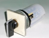
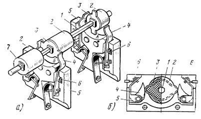
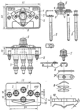
In fig. 1. shows a general view of the PMOV switch and a diagram of its operation, showing that the handle has three positions "Enable" B, "Disable" O and "Neutral" H, to which the switch is automatically returned after each operation.
Rice. 1. PMOV type switch: a — general view, b — working diagram
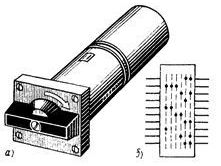
Rice. 2.Key type MKS VF: a — general view, b — working diagram
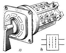
Rice. 3. Package switches and open-type switches of all sizes: 1 — lower bracket for individual sections, 2 — upper bracket for fastening packages, 3 — package, 4 — switching mechanism, 5 — roller, 6 — handle
In fig. 2 shows a general view and diagram of the operation of the MKSVF type switch; to turn on the switch, the handle of the control switch is moved from the O position to the «On» B1 position and then to the «On» B2 position. The operator then releases the handle and the switch automatically switches to the «On» position B. In fig. 3 shows packet switches and open type switches of PVM and PPM types.
Signal blocking contacts (auxiliary contacts) of types SBK and KSA (Fig. 4) are of great importance in control and signaling circuits. Clamps are used to connect the wires of control cables and wires to secondary devices: normal type KN-ZM (Fig. 5), test types ZSCH and KI-4M (Fig. 6 and 7). Widely used for remote control, automation, interlocking and signaling buttons types: K-03 with one pair of NO contacts and one pair of NC contacts, K-23 with two pairs of NC contacts, K-20 with two pairs of NO contacts, etc.
Rice. 4.Connecting auxiliary contacts: a — SBK type auxiliary contact: 1 — axis of the movable contact system (in the places of its attachment — the axis of a square section), 2 — plastic bushings with a protrusion on one side in the form of a square, 3 — movable contact plates with a square hole for inserting the sleeve, 4 — fixed contact plates, 5 — porcelain pads in which the fixed contacts are fixed, 6 — spiral springs pressing the fixed contacts to movable ones, 7 — nuts tightening the movable contact system (sleeves, movable contacts), b — auxiliary contact type KSA: 1 — hexagonal axis, 2 — washer mounted on the axis, 3 — copper ring with two semicircular protrusions pressed into the washer , 4 — brass contacts, 5 — steel springs pressing brass contacts to the protrusions of the copper ring, 6 — clamps for connecting the cores of the cables (conductors)
The test units are electrical connectors (plug connectors) for four (BI-4) or six (BI-6) circuits for operation at a nominal voltage of up to 220 V DC and 250 V AC with a frequency of 50 Hz in stationary electrical installations. They are designed for a rated current of 5 A, a continuous current of 15 A and a current of 300 A for 1 s, for a test voltage of 2500 V.
Test blocks are designed to connect devices for relay protection and automation and measuring devices to secondary circuits of CT (if necessary, VT), as well as to auxiliary current circuits.
The constructions of the four-pole (Figure 8) and six-pole test blocks are the same. The working cover of the device is placed at the base of the test block in working condition. In this position, normal operation of the test unit is carried out with relays and instruments on.The lid block must be sealed.
To switch to another mode of operation, for example, the test mode of the relay protection, the seal is removed and the working cover is replaced with a test one. All circuits are opened, relays and devices are de-energized and at the same time CT current clamps are automatically closed by plate 6.
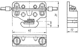
Rice. 5. Clamp type KN-ZM
Rice. 6. ZSCHI type tightening test: a — jumper in the "closed" position, b — the same in the "open" position, 1 and 2 — screws, 3 — jumper, 4 — contact plate for connection with an adjacent bracket
Particular attention should be paid to the smooth removal and installation of the working and test covers at the base of the device and the inadmissibility of their distortions. Violation of these rules can lead to serious accidents.
In case of a long stay of the unit without a working or test cover, the base of the unit is closed with an empty cover to protect dust and live parts from contact. The blank lid is painted in a distinctive color.
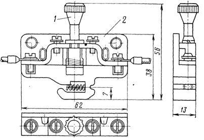
Rice. 7. Test clamp type KI -4M: 1 — plug contact, 2 — screw
Installation of test units in switchgear cabinets requires heating cabinets. The outputs of the blocks allow the connection of copper wires with a cross section of 2.5-4 mm2.
Taking into account the available emergency statistics during the operation of the BI, it is recommended to carefully check the correctness of the installation of the closing plates at the base of the block; during the adjustment of the circuit when installing the test cover at the base of the block, it is necessary to check the assembled circuit especially carefully, paying attention to the inadmissibility of breaking the CT circuits.An example of the inclusion of BI in the scheme is shown in Fig. 5.
BI maintenance consists of periodic inspection and tightening of contact screws, testing with test voltage.
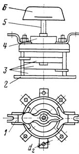
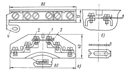
The contact strip type KNR-3 is a three-position non-automatic disconnecting device for a nominal voltage of 380 V AC and 220 V DC with a nominal current of up to 10 A. It is produced for the rear connection of conductors with copper conductors with a section of 2.5 and 4 mm2 (fig. nine ).
These and other similar pads are used by personnel to fix the preset mode of operation of devices for relay protection and automation. For example, a movable pad contact may have three positions: signal, trip, neutral or trip with OAPV, trip without OAPV, signal, two positions: protection enabled, protection disabled in operation, or trip , on signal, etc.
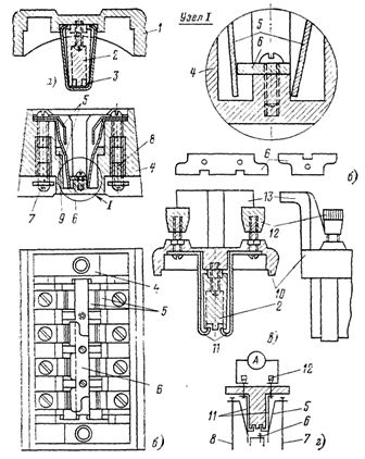
Rice. 8. Test block type BI -4: a — working cover, b — base (section and plan) of the test block, c — test cover, d — diagram of the test block with the test cover in place and the ammeter connected: 1 — plastic box, 2 — plastic insert, 3 — contact plate, 4 — block housing, 5 — double main contact plates, 6 — short plate, 7 — clamps for connecting secondary circuits of CT or VT, or auxiliary circuits, 8 — clamps for connecting protective devices or tools, 9 — spring, 10 — plastic housing of the cover, 11 — contact plates, 12 — clamps for connecting test circuits or measuring devices, 13 — grip of the cover.
Rice.nine. Contact pad type KNR -3: 1 — plastic base, 2 — screws for fixing the pad to the panel, 3 — live screws with pressed L-shaped contact plates, 4 — movable contact, 5 — plastic handle for rotating the movable contact, 6 — U-shaped contact, 7 — contact insert, 8 — arc spacer spring, 9 — current flow — axis of the movable contact, 10 — spring preventing random rotation of the movable contact.