Rated primary and secondary voltage of the transformer
 Nominal primary voltage transformer is called such a voltage that must be supplied to its primary winding in order to obtain the secondary nominal voltage indicated in the passport of the transformer at the terminals of the open secondary winding.
Rated secondary voltage is the voltage applied to the terminals of the secondary winding when the transformer is no-load (voltage is applied to the terminals of the primary winding and the secondary winding is open) and when the rated primary voltage is applied to the primary winding.
The secondary winding voltage changes with the load because the load current creates a voltage drop across the active and inductive resistance of the winding. This change in the secondary voltage depends not only on the magnitude of the current and the resistance of the winding, but also on the power factor of the load (Fig. 1). If the transformer is loaded with purely active power (Fig. 1, a), then the voltage, compared to other options, varies within smaller limits.
In vector diagram E2- EMF.in the secondary winding of the transformer. The secondary stress vector will be equal to the geometric difference:
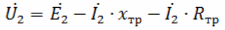
where I2 is the current vector in the secondary winding; хtr and Rtr - respectively the inductive and active resistance of the secondary winding of the transformer.
With an inductive load and at the same current value, the voltage decreases to a greater extent (Fig. 1, b). This is due to the fact that the vector I2 NS xtr lagging behind the current by 90 °, in this case more sharply turned to the vector E2 than in the previous one. With a capacitive load, an increase in the load current causes an increase in the voltage in the transformer winding (Fig. 2, c). In this case, the vector I2 NS xtr equal in length to a similar vector in the first two cases and also lagging behind the current by 90 °, due to the capacitive nature of this current, it turns out to be rotated along the vector E2, and increases the length of U2 compared to E2 .
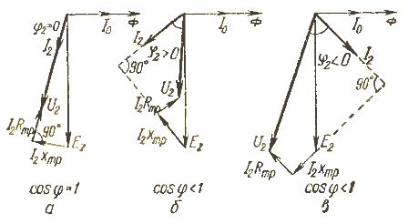
Rice. 1. Change of the secondary voltage of the transformer U2 depending on the power factor of the load (angle φ): a — with an active load; b — with inductive load; c — with capacitive load; E2 — EMF. in the secondary winding of the transformer; I2 — current in the secondary winding (load current); I0 is the magnetizing current of the transformer; Ф — magnetic flux in the core of the transformer; Rtr Xtr — active and inductive resistance of the secondary winding.
During operation, it is necessary to adjust the voltage of the transformer winding. This is achieved by varying the number of turns of the high voltage coil. By changing the number of turns of this coil included in the high voltage circuit, you can change transformation factor in the range of ± 5 to ± 7.5% of the nominal value.
The diagram of taps from windings with simple switching is shown in figure 2. In accordance with these taps, the minimum high voltage, nominal and maximum are indicated in the passport. If, for example, the rated secondary voltage of the transformer is 10,000 V, then the maximum voltage 1.05Un = 10500 V, and the minimum voltage 0.95Un = 9500 V.
For a nominal voltage of 6000 V, we have 6300 and 5700 V, respectively. The number of turns of the high-voltage winding is changed with a switch, the contacts of which are located inside the transformer, and the handle is brought to its cover.
Usually, for transformers that are installed near a step-down substation 35/10 kV or a step-up substation 0.4 / 10 kV, the transformation factor is assumed to be 1.05xKn, that is, put the tap switch in the + 5% position. If the consumer substation is removed from the area, a significant voltage loss occurs in the power line, so the switch is set to the -5% position. The transformer in the middle of the transmission line is set to the nominal transformation ratio (Fig. 3).
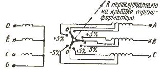
Rice. 2. Scheme of taps from part of the turns for measuring the transformation coefficient with ± 5%
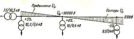
Rice. 3. Installation of a switch of transformer turns depending on the distance of the consumer transformer substation from the feeder regional substation.
Currently, the industry has mastered the production of power transformers with a unit capacity of 25, 40, 63, 100, 160, 250, 400 kVA, etc. For voltage regulation, new transformers are equipped with off-circuit tap-changers or load switches.PBV stands for: switching windings without excitation, that is, with the transformer turned off.
Taps from the coils allow by switching them to change the voltage in the range from -5 to + 5% every 2.5%. Load switching device means: voltage regulation under load (automatic). It allows you to adjust the voltage in the range of -7.5 to + 7.5% in six steps or every 2.5%. Transformers of 63 kVA and above can be fitted with such devices. The designation of a transformer with such a device is TMN, TSMAN.
Three-phase transformers TM and TMN for energy transformation from 20 and 35 kV to 0.4 kV have capacities of 100, 160, 250, 400 and 630 kVA.