Description, device and installation of the automatic switch AE 2040M
Marking of automatic switches AE 20
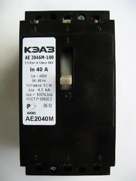
 Let's first understand the labeling of the circuit breaker. The numbers indicating specific performances will be replaced by the letters of the Latin alphabet: АЕ 204X M YZ0 NNA 12In У3,
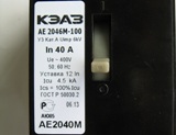
For example, the presented machine (see photo on the left): AE 2046 M 100 40A 12 V U3,
Where AE 20 is a conventional switch brand designation;
4 — a number indicating the highest rated current of the 63A series; X — designation of built-in disconnecting devices:
6 — combined protection through a thermal and electromagnetic disconnection device;
M — letter indicating modernization (for AE 2046 this is a small-sized version);
Y — number indicating additional contacts: 1 — no contacts; Z — indication of the presence of shunt release: 0 — not supplied;
0 — a digit marking the lack of regulation of the thermal release device (for example, such a setting is present in the AP50B breaker); NN is the numerical value of the rated current in amperes;
12In is the overcurrent value at which an electromagnetic release-initiated instantaneous trip occurs (for the proposed device, the setting is 12 • 40 = 480 amperes, where 40 is the rated current of the circuit breaker presented);
U3 — it is allowed to work in a moderate macroclimatic region when it is installed in covered rooms with natural ventilation without regulation of temperature conditions (according to the climatic standard GOST 15150-69).
The main purpose of the circuit breaker AE 2046M
The circuit breaker serves the following purposes:
• transmission of electrical energy during normal operation, which can last for a long period (months of operation);
• power interruption in case of overcurrent detection (instant operation in case of short circuit and delayed protective shutdown in case of overload);
• manual switching of the output circuit by the operator no more than 3 per hour.
The switching devices of the AE 20 series meet the requirements and are tested in accordance with the provisions of the normative document GOST R 50030, part 2 (the original text of the standard IEC 60947.2).
AE 20 breaker device
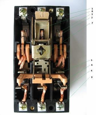
The photo above shows the appearance of «filling» the switch with the top protective cover removed:
• housing of switch 1 made of self-extinguishing plastic, which protects a person from contact with current-carrying elements;
• main group of contacts, consisting of removable 2 and fixed 3 contacts (as you can see, their three pairs are a three-pole device);
• thermal release 4, made on the basis of a bimetallic plate;
• electromagnetic release (only part of the device 5 is visible, which is able to rotate the partition);
• rotating release rail 6, which can be influenced by the release devices, thereby actuating the trigger mechanism;
• free release mechanism 7 (or trigger mechanism), serving for operational mechanical divergence of contacts 2 and 3 in the short-circuit or overload zone, as well as during manual action;
• arc chute 8;
• contact clamps 9 at the base of the screw;
• in this version are not provided, but may be present: shunt release and / or additional contacts.
In general, the circuit breaker components are the units presented above, then we will analyze each in turn.
A main contact group (see photo below) meets conflicting requirements for minimum electrical resistance and durability. To ensure free flow of current at the connection point, a material with high electrical conductivity, such as silver (Ag) or copper (Cu), is required.
But silver is a soft metal with a low melting point (962 ° C), which will quickly burn under the action of an electric arc. Copper has a lower conductivity, with a melting point of 1083 ° C, but has an unpleasant property — the formation of a dielectric oxide film in air. And to meet the wear resistance requirement, a strong metal such as alloy steel is needed. To take these factors into account, a composite material with silver inclusions is used.
Thermal release It is made on the basis of bimetal, which when heated bends to a material with lower thermal expansion (heat is released when current flows). The impact on the release mechanism is by means of a rotating rail 6.The response time of the device is inversely dependent on the current strength and can vary from a few seconds to an hour.
Electromagnetic release has a time-tested design on the principle of an electromagnet — a current flows through the copper turns, which, when a predetermined threshold is exceeded, generates a magnetic field that moves the armature. The process takes up to 0.2 seconds along with the time required to separate the main contacts.
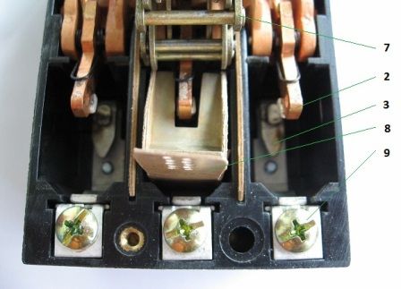
An arc arrester (shown in the figure below) absorbs the effect of an electric arc. It consists of profiled steel plates that are mounted on cardboard and insulated from each other. The nature of the arc pushes it to look for ways of minimal resistance - according to this factor, steel has an advantage over air. Here the electric arc falls into a «trap» — it enters the plates, loses thermal energy (cooling) necessary for ionization, and goes out.
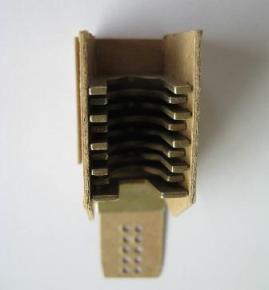
Circuit Breaker Arc Chute
Threaded terminals serve to connect incoming and outgoing wires. Copper and aluminum wires, as well as rigid or flexible with a cross-sectional area of 1.5 to 25 mm2, can be fastened.
Installation of block breaker AE 2046M
The switch is secured with two screws throughout the body. To connect the wires, it is not necessary to remove the cover.
Installation is carried out on a vertical surface with the inscription «I» upwards, with a possible deviation of ± 90º in any direction.
Before installation, they are convinced of the integrity of the box, and also perform several control switches on and off, which should not be accompanied by jamming or other mechanical defects.
The input circuit from the source should be connected to the upper terminals 1, 3 and 5.