Lightning protection of overhead lines with a voltage of up to 1000 V
 Protection of overhead lines up to 1000 V from direct lightning strikes is not required. However, the lines themselves connected to electrical equipment in buildings can serve as a channel for the introduction of high potentials during direct lightning strikes in the line, as well as induced in the conductors due to electrostatic and electromagnetic induction during nearby lightning discharges.
Overvoltage can reach hundreds of thousands of volts and cause insulation breakdown of wires and electrical equipment and fires. They are dangerous to the lives of people in buildings and facilities that are supplied with electricity through an overhead line.
The supply of overhead lines for outdoor lighting, electric mains with a voltage of up to 1000 V, radio transmission lines and alarms for searchlight masts, chimneys, cooling towers and other large buildings and structures is not permitted. Use cables here.
To protect against lightning, overhead lines in residential areas with one- and two-story buildings that are not protected by boiler chimneys, tall trees, buildings, etc., must have grounding devices.Earthing resistance — not more than 30 Ohm. Distances between groundings for areas with an average annual number of lightning hours up to 40 are 200 m.
For areas where the average annual number of hours with thunderstorms is more than 40, grounding is organized every 100 m. In addition, grounding devices are carried out:
• on supports — with branches to the entrances of public buildings and premises where a large number of people can be located (schools, clubs, nurseries, hospitals, canteens, dormitories in pioneer camps, etc.) or have a large economic value (cattle) premises, warehouses, workshops, etc.);
• on the terminal supports of lines with branches to the entrances of buildings of any purpose. It is necessary to attach hooks and pins from wooden and reinforced concrete supports to the specified grounding devices, as well as the reinforcement of the latter.
In both cases, it is recommended to install it on supports as well valve restrictors.
In networks with an earthed neutral, earthing devices must be used to re-earth the neutral conductor for earthing against atmospheric surges.
Ground hooks and pins
In networks with a grounded neutral, the hooks and pins of the phase conductors on reinforced concrete supports, as well as the reinforcement of these supports, must be connected to a grounded neutral conductor (see Fig. 1).
This is done so that the overvoltage occurring in lightning discharges causes an overlap from the wire to the hook and the charge goes to earth on the neutral wire through the nearest protective earthing of the neutral wire.In this case, the magnitude of the overvoltage is reduced to 30-50 kV, the risk of damage and overlapping of the insulation in buildings connected to overhead lines is reduced.
Hooks and pins on wooden poles do not need to be grounded (except for surge grounding poles mentioned above). In networks with an isolated neutral, the hooks and pins of the phase conductors on reinforced concrete supports, as well as the reinforcement of these supports, must be grounded. Earthing resistance not more than 50 Ohm, Earthing and neutral protective conductors made of steel must have a diameter of at least 6 mm.
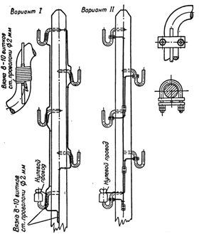
Fig. 1. Earthing hooks from overhead lines 0.4 kV
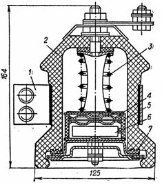
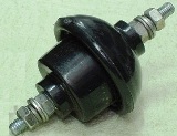
Rice. 2. Valve limiter RVN -0.5: 1 — fastening bracket; 2 — insulator; 3 — spring; 4 — single spark; 5 — paper-bakelite cylinder; 6 — working resistor disk; 7 — sealing rubber ring
Valve restrictors
In order to reduce overvoltage in the wires of overhead lines, low-voltage valve limiters of the RVN-0.5 type of domestic production and similar imported ones (for example, GZ a-0.66) are used. Surge arresters are a very effective means of reducing surges. The surge impulse wave coming from the line is deflected to the ground, the remaining voltage does not exceed 3–3.5 kV, which is practically safe for electrical equipment.
The limiter RVN-0.5 for external and internal installation (Fig. 2) consists of a single spark and a working resistance (resistor) connected in series with it, covered with a porcelain hermetic cover and compressed by a cylindrical spring. Sealing is done with an ozone-resistant rubber ring.
The arrester is connected to the phase wire and the grounded outlet.Its protective effect consists in the fact that when an overvoltage occurs, the spark gap is destroyed, the impulse current flowing through the arrester, due to the non-linear characteristic of the operating resistance, reduces the magnitude of the overvoltage wave to a value of 3-5 kV, which is safe for the equipment. The spark gap is chosen in such a way that it breaks every time as soon as the voltage in the protected area exceeds the permissible value.
After the breakdown of the spark gap of the arrester, the current flowing under the action of the frequency voltage of the power (the so-called Follow-on current) is interrupted by the spark gap at the first crossing of zero. This completes the work of the arrester and it is ready for action again.