Types of frequency converters
Devices called frequency converters are used to convert mains AC voltage with an industrial frequency of 50/60 Hz into AC voltage of a different frequency. The output frequency of the frequency converter can vary widely, typically from 0.5 to 400 Hz. Higher frequencies are unacceptable for modern motors due to the nature of the materials from which the stator and rotor cores are made.
Any kind frequency converter includes two main parts: control and power supply. The control part is a circuit of a digital microcircuit that provides control of the switches of the power unit, and also serves to control, diagnose and protect the driven drive and the converter itself.
The power supply section directly includes the switches — powerful transistors or thyristors. In this case, frequency converters are of two types: with a highlighted section of direct current or with direct communication. Direct-coupled converters have an efficiency of up to 98% and can operate with significant voltages and currents.In general, each of the two types of frequency converters mentioned has individual advantages and disadvantages, and it may be rational to apply one or the other for different applications.
Direct communication
Frequency converters with direct galvanic connection were the first to appear on the market, their power section is a controlled thyristor rectifier, in which certain groups of locking thyristors are opened in turn, and the stator windings are connected in turn to the network. This means that ultimately the voltage supplied to the stator is shaped as pieces of a mains sine wave which are fed in series to the windings.
The sinusoidal voltage is converted to a sawtooth voltage at the output. The frequency is lower than the mains — from 0.5 to about 40 Hz. Obviously, the range of this type of converter is limited. Non-locking thyristors require more complex control schemes, which increases the cost of these devices.
Parts of the output sine wave generate higher harmonics, and these are additional losses and overheating of the motor with a decrease in shaft torque, in addition, not weak disturbances enter the network. If compensating devices are used, then again costs increase, dimensions and weight increase, and converter efficiency decreases.
The advantages of frequency converters with direct galvanic coupling include:
- the possibility of continuous operation with significant voltages and currents;
- impulse overload resistance;
- Efficiency up to 98%;
- applicability in high voltage circuits from 3 to 10 kV and even higher.
In this case, high-voltage frequency converters are, of course, more expensive than low-voltage ones. Previously, they were used where needed — namely direct-coupled thyristor converters.
With DC connection highlighted
For modern drives, frequency converters with a highlighted DC block are more widely used for frequency regulation purposes. Here, the conversion is done in two steps. First, the input mains voltage is rectified and filtered, smoothed, then fed to the inverter, where it is converted into alternating current with the required frequency and voltage with the required amplitude.
The efficiency of such a double conversion decreases and the dimensions of the device become slightly larger than those of converters with direct electrical connection. The sine wave is generated here by an autonomous current and voltage inverter.
In DC link frequency converters, latching thyristors or IGBT transistors… Locking thyristors were mainly used in the first manufactured frequency converters of this type, then, with the appearance of IGBT transistors on the market, it was converters based on these transistors that began to dominate among low-voltage devices.
To turn on the thyristor, a short pulse applied to the control electrode is sufficient, and to turn it off, it is necessary to apply a reverse voltage to the thyristor or reset the switching current to zero. A special control scheme is required — complex and dimensional. Bipolar IGBT transistors have more flexible control, lower power consumption and quite high speed.
For this reason, frequency converters based on IGBT transistors have made it possible to extend the range of drive control speeds: asynchronous vector control motors based on IGBT transistors can safely operate at low speeds without the need for feedback sensors .
Microprocessors coupled with high-speed transistors produce fewer higher harmonics at the output than thyristor converters. As a result, the losses turn out to be smaller, the windings and the magnetic circuit overheat less, the rotor pulsations at low frequencies are reduced. Less losses in capacitor banks, in transformers - the service life of these elements increases. There are fewer errors at work.
If we compare a thyristor converter with a transistor converter with the same output power, then the second one will weigh less, be smaller in size, and its operation will be more reliable and uniform. The modular design of IGBT switches allows for more efficient heat dissipation and requires less space for mounting power elements, in addition, modular switches are better protected from switching surges, that is, the probability of damage is lower.
Frequency converters based on IGBTs are more expensive because power modules are complex electronic components to manufacture. However, the price is justified by the quality. At the same time, statistics show a tendency to decrease the prices of IGBT transistors every year.
The principle of operation of the IGBT frequency converter
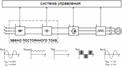
The figure shows a diagram of a frequency converter and graphs of currents and voltages of each of the elements. Mains voltage of constant amplitude and frequency is fed to the rectifier, which can be controlled or uncontrolled. After the rectifier there is a capacitor - a capacitive filter. These two elements—a rectifier and a capacitor—form a DC unit.
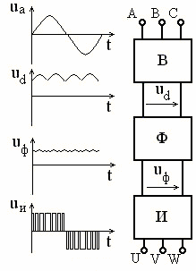
From the filter, a constant voltage is now supplied to an autonomous pulse inverter in which the IGBT transistors work. The diagram shows a typical solution for modern frequency converters. The direct voltage is converted into a three-phase pulse with adjustable frequency and amplitude.
The control system gives timely signals to each of the keys, and the corresponding coils are sequentially switched to the permanent connection. In this case, the duration of connecting the coils to the connection is modulated to sine. So, in the central part of the half-period, the width of the pulse is the largest, and at the edges - the smallest. It's happening here pulse width modulation voltage on the motor stator windings. The frequency of PWM usually reaches 15 kHz, and the coils themselves work as an inductive filter, as a result of which the currents through them are almost sinusoidal.
If the rectifier is controlled at the input, then the amplitude change is done by controlling the rectifier, and the inverter is only responsible for frequency conversion. Sometimes an additional filter is installed at the output of the inverter to dampen current waves (very rarely this is used in low-power converters).Either way, the output is three-phase voltage and AC current with user-defined basic parameters.