Grounding devices for distribution substations — purpose, design characteristics, operational characteristics
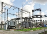 The electrical equipment of the distribution substations during normal operation is in good technical condition and does not pose a danger to people. The metal parts of the housing are isolated from live parts of the equipment. But in the event of an accident in the electrical network, which is accompanied by a breakdown of the insulation of the equipment or a short circuit of one of the phases of the network to the ground, a person who comes into contact with the equipment or is in close proximity to it will be exposed to electric current blow.
A current of 90-100 mA and more acting on the human body for a fraction of a second is fatal. The severity of an electric shock also depends on the paths of the current and the physiological characteristics of the human body, which is why the current can often be fatal and of a smaller magnitude.
To prevent electric shock to personnel servicing electrical installations, the metal parts of the equipment housings, as well as the metal elements in the immediate vicinity of the equipment, must be grounded.
Grounding implies the connection of metal elements, equipment boxes with the grounding circuit of an electrical installation, in this case a substation.
Let's list which items of equipment of distribution substations are grounded:
-
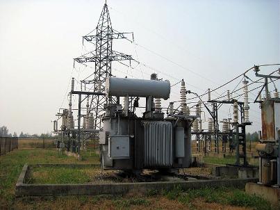
power transformer tank;
-
engine housing;
-
high voltage tank;
-
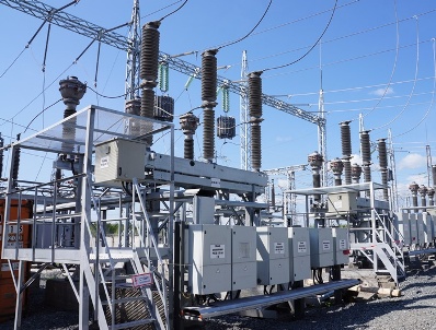
metal elements of portal busbars carrying structures of disconnectors, separators and other equipment of switchgear;
-
doors, fences, backboard enclosures, equipment cabinets;
-
metal armor of cable lines regardless of purpose (power supply, secondary switching), end and connecting cable bushings with a metal case;
-
secondary windings of current transformers and voltage transformers;
-
metal smooth-walled and corrugated pipes in which electrical wires and other metal boxes of existing equipment and electrical installations are laid.
Features of the design of the grounding device of the substation
The grounding device of a substation structurally consists of two main elements — a grounding electrode and grounding conductors (grounding busbars).
Earthing switch These are metal elements that come into direct contact with the ground. Earthing switches, in turn, are of two types — natural and artificial.Natural grounding conductors include various metal structures, some of which enter the ground, pipelines for various purposes (except for gases and other pipelines through which flammable liquids flow), metal sheaths (armors) of cable lines laid in the ground. Artificial ground wires are made by burying steel pipes, rods, strips, angle steel in the ground.
Grounding wires connect the metal parts of the equipment and other grounded elements to the grounding electrode. That is, through the grounding wires occurs equipment grounding.
Equipment enclosures, equipment support structures, etc. are grounded using rigid metal busbars. The grounding bars are colored black. Provision must be made for the installation of portable protective earths at certain locations along the earthing busbars and on earthed metal elements. These places are cleaned, covered with a lubricant to prevent oxidation of the metal, near these places are installed in the form of a ready-made sign or a ground sign is applied with paint.
Portable protective earthing consist of flexible copper wires connected to grounded and grounded elements using special clamps. Portable groundings play the role of grounding wires, they are used to ground sections of the electrical network to ensure safety during repair work, to ground special equipment that is used to perform work within an electrical installation or in close proximity to power lines.
The movable elements of the equipment — doors of cabinets, fences, fixed grounding fins of disconnectors, etc., to ensure reliable contact with the grounded body of the cabinet or supporting structure, are connected with flexible copper wires.
The connection of metal grounding bars to grounding structures is carried out by welding. The connection of the grounding busbars to the housings of the equipment, depending on its design characteristics, can be carried out both by welding and by means of bolted connections. Copper grounding conductors of movable equipment elements are connected to grounded elements by bolted connections or soldering, if it is necessary to connect a copper conductor to the metal sheath of the cable line.
Features of the operation of grounding devices
There are standardized values for the resistance of earthing devices. Depending on the operating voltage of the electrical installation, the level of earth fault currents, the permissible maximum resistance of the grounding circuit of the substation can vary from 0.5 to 4 ohms.
During operation, grounding devices must be checked periodically. The inspection is carried out at least once every 6 years and consists of two stages — measuring the resistance of the grounding device and randomly checking the condition of the grounding wires.
Also, during the operation of electrical equipment, it is necessary to periodically clean the places of installation of portable protective earthings from rust and cover them with a new layer of grease to prevent corrosion.