What is earth resistance
 The grounding device has a resistance. Earth resistance consists of the resistance that the earth has to the passing current (leakage resistance), the resistance of the earthing conductors and the resistance of the earth electrode itself.
The resistances of the earth conductors and the earth electrode are usually small compared to the splash resistance and in many cases can be neglected, given that the earth resistance is equal to the splash resistance.
The earth resistance value must not be increased more than a certain value determined for each installation, otherwise the maintenance of the installation may become unsafe or the installation itself may end up in operating conditions for which it was not designed .
All electrical equipment and electronics are built around some standardized ground resistance values—0.5, 1, 2, 4.8, 10, 15, 30, and 60 ohms.
1.7.101.The resistance of the earthing device to which the neutrals of the generator or transformer or the terminals of the single-phase current source are connected, at any time of the year should be not more than 2 — 4 and 8 ohms, respectively, on line voltages of 660, 380 and 220 V on the three-phase current source or 380.220 and 127 V single-phase current source.
The resistance of the grounding electrode located in close proximity to the neutral of a generator or transformer or the output of a single-phase current source must be no more than 15, 30 and 60 ohms respectively at a line voltage of 660, 380 and 220 V of a three-phase current source or 380, 220 and 127 V on a single-phase current source. (PUE)
Earthing resistance can vary greatly due to various reasons such as weather conditions (rain or dry weather), season, etc. Therefore, it is important to periodically measure the ground resistance.
If a voltage U is applied to two electrodes (single tubes) located in the ground at a great distance (several tens of meters), the current will flow through the electrodes and the ground Az (oriz. 1).
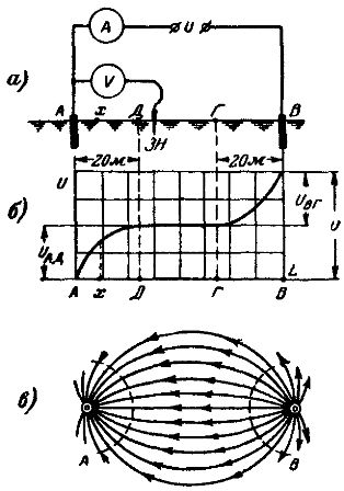
Rice. 1. Distribution of potentials between two electrodes on the surface of the earth: a — circuit for finding the distribution of potentials; b — voltage drop curve; c — diagram of the passage of currents.
If the first electrode (A) is connected to one clamp of the electrostatic voltmeter and the second clamp is connected to ground by means of an iron rod probe at various points on a straight line connecting the electrodes, then the voltage drop curves can be get a hundred lines connecting the electrodes. Such a curve is shown in fig. 1, b.
The curve shows that near the first electrode the voltage first increases rapidly, then more slowly and then remains unchanged. Approaching the second electrode (B), the voltage begins to increase slowly at first, then more rapidly.
This voltage distribution is explained by the fact that the current lines from the first electrode diverge in different directions (Fig. 1), the current spreads, and therefore, with the distance from the first electrode, the current passes through the ever-increasing sections of the ground. In other words, with the distance from the first electrode, the current density decreases, reaching at a certain distance from it (for a single pipe at a distance of about 20 m) values so small that it can be considered equal to zero.
As a result, for a unit length of the current path, the ground has unequal current resistance: more — near the electrode and less and less — with distance from it. This leads to the fact that the voltage drop per unit path decreases with the distance from the electrode , reaching zero when the distance from one pipe is greater than 20 m.
As the second electrode is approached, the flux lines converge, so that the resistance and voltage drop per unit current path increase.
Based on the above, under the splash resistance of the first electrode, we will understand the resistance encountered on its way in the entire layer of the earth adjacent to the electrode (in the current splash zone) on which the voltage drop is observed.
Hence the resistance value of the first ground
ra = Hell/I
If there is a voltage Uvg on the ground layer in close proximity to the second electrode, then the resistance of the second ground
rc = Uvg /I
Points on the earth's surface in the zone where no voltage drop is observed (DG zone, Fig. 1) are considered as zero-potential points.
Under this condition, the potential φx at any point x in the current spreading zone will be numerically equal to the voltage between that point and the point of zero potential, for example point D:
UxD = φx — φd = φx — 0 = φx
According to the above, the potentials of electrodes A and B, called common potentials, are equal:
φa = UAD and φv = Uvg
The potential distribution curve on the earth's surface along the line connecting electrodes A and B is shown in fig. 2.
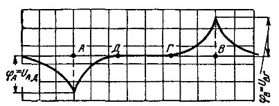
Rice. 2. Potential distribution curve on the earth's surface
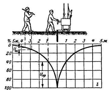
Rice. 3. Determination of potential distribution curve and touch voltage
The shape of this curve does not depend on the current, but on the shape of the electrodes and their placement. The potential distribution curve makes it possible to determine at what potential difference a person will be touching two points on the ground or to a grounded point of the installation and any point on the ground. Thus, this curve makes it possible to assess whether the earthing guarantees the safety of people in contact with the installation.
Earthing resistance measurement can be done using different methods:
-
ammeter and voltmeter method;
-
by the method of direct accounting using special ratios;
-
by compensation method;
-
bridging methods (single bridges).
In all cases of grounding resistance measurement, it is necessary to use alternating current, because when using direct current, polarization phenomena will occur at the point of contact of the grounding electrode with wet earth, which significantly distorts the measurement result.
Also read on this topic: Measurement of the resistance of the protective earth loop