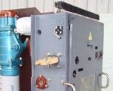
Maintenance of control and signaling devices for substation switchgear
Control and signal circuits
 At substations, remote and automatic control of circuit breakers and other devices is widely used. The essence of these control methods lies in the fact that from the control point (central or local control panel) a signal is sent through the cable communication line, acting on the executive organ of the device (for example, a switch), the position of which must be changed.
This signal can be given by the operator, relay protection devices, automation, etc. At the same time, with the help of light and sound signals, the position of the switching equipment is monitored under normal conditions, the emergency shutdown of the electrical equipment is signaled, etc. n. devices, below are the schemes of operation of some of them, with the help of which it is carried out:
• management of various switching equipment (switches, disconnectors, etc.),
• signaling of the technical condition of the electrical equipment under normal, emergency and other operating conditions.
When familiarizing yourself with the following control and signaling schemes, it should be borne in mind that in them the position of all contacts is indicated for the off position of the equipment and in the off state of the relay and contactor windings.
Control and signaling devices for oil switches
In fig. 1 shows, for example, a simplified oil switch control and signaling scheme, with switch position light signaling and control circuit light monitoring. If an emergency shutdown of any link is required due to a fault occurring, the command signal is sent from the relay protection via the relay protection contact (Fig. 1).
However, if it is necessary to reactivate the line or transformer after a short time (as is common in electrical networks) after they have been disconnected from protection (the cause of the fault or interruption may disappear during this time), then the command signal to close the circuit breaker is supplied by the automatic closing device which closes the PA contact...
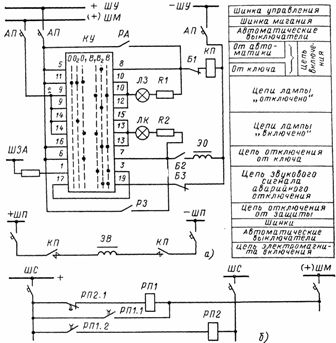
Figure 1. Control circuits of the switch with light control of the control circuits: a — control and signaling circuit, b — flashing device circuit
Signaling the position of the switch (or other device) can be done by a light signal, and signaling a change in its position — by a sound signal.
The control circuit is powered by DC from the battery.The above diagram allows you to monitor the health of the circuit of the subsequent operation and corresponds to the off state of the circuit breaker and the O «Disabled» position of the control switch KU. In this case, contacts 11 and 10 of the KU switch are closed. On the control panel, the lamp LZ, connected in series with the additional resistor R1 and the winding of the intermediate contactor of the gearbox, glows with a constant light, which indicates the integrity of the switching circuit and the on position of the AP breaker.
In this case, the contactor KP cannot turn on, because the current in its winding, limited by the resistances of the resistor R1 and the lamp LZ, is insufficient to activate it. The resistors in the circuit of the lamp LZ and LK turn on, so if they are damaged , there is no false switch on or off. To turn on the switch, the KU key is moved to position B1. The LZ lamp receives power from the (+) CMM bus (the so-called flashing plus) and starts flashing. Before tracing further operations with the KU key, let's look at why the lamp blinks in this case.
The fact is that a special device called a pair of pulses is connected to the (+) CMM bus, the diagram of which is shown in fig. 1, b. In the event of a discrepancy, that is, when the switch is in the off position, and its control switch KU is in position B1, the contact of the relay RP2.1 in the circuit of the coil RP1 closes, a circuit is created: bus + AL, contact RP2.1, relay RP1, bus (+) ShM, contacts 9-10 of the switch KU (Fig. 1, a), LZ lamp, resistor R1, auxiliary contact of switch B1, contactor coil KP, bus — SHU.
The LZ lamp will burn with an incomplete glow. Relay RP1 will operate where both contacts close without time delay.One of them (RP1.1) will close the coil of its relay RP1 and the lamp LZ will light up at full brightness, the other (RP1.2) will close the circuit of relay RP2, which will cause its contact in the RP1 circuit to open, which will open its contacts with a time delay, the LZ lamp will go out. The relay RP2 will then be turned off, and its contact RP2.1 in the circuit RP1 will close with a time delay, after which the lamp LZ will turn on again.
Thanks to such a scheme of a pair of pulses, the lamp lights up in a certain time interval, that is, it flashes. This will continue until the breaker closing operation is complete, causing the breaker position and the KU switch to match.
Let us continue our examination of the circuit shown in Fig. 1, a. From position B1, the key is transferred to position B2, the lamp LZ goes out and the coil of KP receives full voltage through contacts 5-8 of KU. The contactor turns on and closes the circuit breaker closing the electromagnetic circuit. After that, the KU key is transferred to position B («On»). Once the switch is on, the auxiliary contact B1 opens and opens the switching circuit. Another auxiliary contact B2 located in the shutdown circuit closes, as a result of which the lamp LK through contacts 13-16 begins to burn with a uniform light, signaling that the switch and automatic switches of the access point are turned on and the shutdown circuit is in good condition.
To open the breaker, the KU switch is moved from position B ("On") to position O1 ("Pre-off"), and contacts 13-14 are closed. The LK lamp lights up with a flashing light. After that, the key is transferred to position O2 ("Disable"), and contacts 6-7 are closed.
The closed lamp LK goes out, the switch is de-energized by the trip solenoid EO, and the auxiliary contact B2 located in the trip circuit opens, breaking the trip circuit. The LZ lamp glows with constant light. At the same time, the breaker closing circuit is prepared again, because in this circuit, when the breaker is open, the auxiliary contact B1 closes. The KU key returns to the O position.
The following options should be considered when considering this scheme:
1. after opening the circuit breaker, it can be turned on by any automatic devices (AR, ATS, etc.) closing their RA contacts,
2. When the switch is on, it can be disconnected from the relay protection contacts of the relay protection devices. In this case, in the position of discrepancy between the KU control key and the switch, the LK or LZ lamp will flash until the KU key is transferred (confirmed) to the O or B position.
In the circuit, the mismatch position is used to provide an audible signal for the emergency shutdown of the switch due to the fact that in position B of the control switch, contacts 1-3 and 17-19 are closed, and the auxiliary contact B3 of the switch itself will close, when it is disarmed. As a result, the audible alarm circuit from the SHZA bus closes, the siren (or beeper) will sound an audible signal that will continue until the KU key is returned to the O position.
These schemes are implemented with keys to fix the position of the switch ("On", "Off") at substations with constant duty, but with a large number of connections, the staff may not notice the extinguishing of the red or green lamp, signaling a break in the switching circuits and shutdown. In these cases, schemes with robust monitoring of the health of these circuits are used.
At substations where there is no permanent duty, switches are used without fixing the position of the switch. Such keys shown in fig. 2, have only three positions: B - "On", O - "Disable", H - "Neutral", which the key returns to every time after turning to the B or O position.
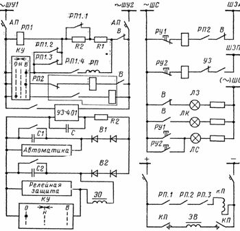
Rice. 2. Control and signaling of the circuit breaker with simultaneous use of operating alternating, direct and direct current: V - auxiliary contacts of the switch.
Schemes for controlling and signaling the position of switches are used in different versions, depending on the type of switch and its drive, the use of automation or telemechanics to control switches and other conditions. In this case, the circuits of the circuits of the working current, as well as the control equipment, are changed.
Thus, in the presence remote control of circuit breakers (on substations without constant load) it is impossible to use a scheme with signaling a discrepancy between the position of the control switch and the position of the switch, since this scheme requires the adjustment of the control switch to the position of the switch after each change in its position.In remote control of the switches, apart from monitoring the on and off circuits, it is also necessary to use separate relays to send warning signals to the DP or to the attendant at home for faults, presence of ground faults, etc.
In the same fig. 2 shows another example of a circuit breaker control scheme, characterized by the fact that alternating current, direct current and rectified current are simultaneously used as a source of operating current. The diagram is shown for a circuit breaker with an electromagnetic drive. The remote control of the circuit breaker is carried out by the alternating current busbars ХУ1 and ХУ2. The UZ-401 device is powered by the same buses designed to receive rectified current and charge capacitor batteries C1 and C2.
When the relay protection trips (closing its contacts), the pre-charged capacitor bank C2 discharges to the tripping solenoid of EO. In this case, the switch is off. The energy of capacitor bank C1 is used to drive automatic devices.
Since the UZ-401 charger operates on two capacitor batteries (there may be more of them), the circuit provides diodes B1 and B2, providing power supply only to the circuit where it is necessary to charge the capacitors in connection with the operation of the protection relay and automation. As in the previous scheme, the power supply to the electromagnet for turning on the EV is carried out by DC buses, since this requires a significant current. The alarm system is powered by an alternating current source.
Let's make some explanations about the diagram:
1. the remote switching on of the circuit breaker is carried out with the KU key.Since in the open position of the switch and in the presence of voltage in the buses of ShU, the relay RP1 will be in the actuated state, then its contact RP1 of the relay circuit RP is closed. When the key KU is turned to position B, the relay RP is activated and with its contacts turns on the contactor KP, as a result of which the voltage is supplied to the electromagnet of EV, it is activated and the switch is turned on.
2. The diagram shows a two-position relay RP2. When the switch is turned on, relay RP2 closes its contact in the alarm circuit, so when the switch is turned off by relay protection (or in the case of spontaneous tripping), relay RU1 is activated, closing its contact, as thus activating the audible alarm (from the SHZA buses).
3. In the event of a malfunction of the UZ charger (the contact of the UZ relay, which controls the device's serviceability, closes), the indicator relay RU2 is activated and an audible warning signal is given (through the SHZP buses). The light signaling of the position of the switch by lamps LZ («Disabled»), LK («Enabled»), LS («Emergency shutdown of the switch and malfunction of the charger») is carried out through the AL buses.
4. Relay RP1 serves to block the circuit breaker from multiple closings in the event of a short circuit. When short-circuiting, the switch is turned off by relay protection, and further short-circuiting becomes impossible, since the RP1 relay will be closed by its contacts.