Operation of TP
 Organization of technical operation. The reliability of the work of the TP depends on the quality of the design and construction and installation works, on the level of its work, which must be carried out in full accordance with the existing guidelines and training materials.
Correct technical operation of TP ensures timely and high-quality maintenance and prevention.
Maintenance and preventive work is carried out to prevent the occurrence and removal of individual damages and defects that occurred during operation. The scope of this work includes system inspections, preventive measurements and TP checks.
Scheduled inspections of TP are produced during the day according to the schedule approved by the chief engineer of the enterprise, but at least once every 6 months.
Emergency checks of TP are carried out after emergency interruptions of power lines, during equipment overload, sudden changes in weather and natural phenomena (wet snow, ice, thunderstorm, hurricane, etc.); such checks are carried out at any time.
Control reviews of TP produced by engineering and technical personnel at least once a year... Usually they are combined with checking of lightning protection devices, acceptance of objects for operation in winter conditions, with a view to VL 6-10 or 0.4 kV, etc. At the same time, the scope of the repair of transformer substations for the next year is specified.
Planned prevention of PPR is divided into current and basic. It is manufactured to maintain the TP in a technically sound condition, ensuring long-term reliable and economical operation by restoring and replacing worn elements and parts.
With the current repair of the TP once every three to four years, all work is carried out to ensure normal operation between major repairs.
In cases that do not suffer a delay before the next major repair, preventive selective repairs are carried out with a single replacement of individual elements and parts of the TP. The work is carried out, as a rule, by operational operational personnel, supported by the assessment of operational waste.
The main repair of the TP is carried out once every six to ten years to maintain or restore the initial working condition of the TP. Worn elements and parts are repaired or replaced with more durable and economical ones to improve the performance of the TP equipment. At the same time, during the overhaul, a complete revision of the TP equipment is carried out with a detailed inspection, the necessary measurements and tests, with the elimination of the revealed shortcomings and defects.
The work is carried out by special repair personnel of the network areas, which is maintained at the expense of the depreciation fund provided for major repairs.The preparation of the TP for putting it into repair, acceptance of this repair and commissioning is carried out by the operational operational staff of the network regions.
Depending on the condition of the structures and equipment of the substation, established through inspections, preventive measurements and inspections, the repair time can be changed with the permission of the management of the power system. Emergency-restorative repairs are carried out when there is a need beyond the approved planned repair.
For a more efficient use of the existing mechanization and a better execution of the work in the shortest possible time, preventive measurements and major repairs in the TP are recommended in a number of cases to be carried out centrally by the forces of specialized personnel (laboratories, workshops, etc.) of the power grid company.
The normal organization of the operation of the TP provides for the systematic maintenance of technical documentation characterizing the electrical equipment and its condition, as well as planning and reporting of the implementation of preventive and repair work in the TP. The list of technical documentation, its content (form) and maintenance procedure are established and approved by the power system management.
One of the main technical documents is the passport repair card of the TP and the passport repair card of the transformers installed on this TP.
The TP passport repair card reflects all technical and design data for the installed equipment, for the performed repairs and reconstructions.It indicates the inventory number, the type and location of the TP installation, the name of the design and installation organization, the date of commissioning of the TP.
An electrical one-line diagram of the TP is drawn in the passport with a detailed indication of the parameters of the installed HV and LV equipment, busbars, lightning protection devices, electrical measuring devices, etc.; the name of the feed lines and user connections is also indicated.
A plan and section of the transformer substation is drawn, indicating the main dimensions and construction materials, with the application of an earth loop (for mast transformer substations and KTP, sections are not required). The passport card records the dates and results of inspections of lightning protection devices, measurements of the resistance of grounding loops, data on repairs and preventive tests of equipment and on the repair of TP structures.
On the front side of the passport repair card of a power transformer (or on the factory form) its main technical data are indicated: inventory and serial numbers, type, diagram and group of connections, year of manufacture and commissioning, power in kilovolt-amperes , rated current and voltage on the HV and LV side, voltage x. NS. and k. z., transformer mass, oil mass, dimensions. The passport also contains information on the reason for removal and the new place of installation of the transformer, information on the installation, removal and reloading of thermosiphon filters and switch positions.
The date and reason for the repair, the volume of work performed, the results of tests and measurements, as well as detected and uncorrected defects, notes on the operation of the TP equipment and the transformer are indicated in the passports-cards of the TP and the transformer. This information is entered in the relevant passport forms no later than 5 days after the completion of the work based on acts and protocols. The passport or form of the transformer is kept together with the passport of the TP in which it is installed. With each movement of the transformer, the passport is transferred along with the transformer.
In order to determine the possibility of connecting new consumers and the need to replace transformers and TP equipment, it is recommended to keep a register of consumers and measurements of currents and voltages in the TP for the TP area (section). The log records for each TP the results of the measurement of the load currents of all LV connections, the total load of the transformer and its unevenness by phases, as well as the voltage value of the TP busbars. Measurements are carried out on the 0.4 kV side 2-3 times a year at different times of the year and day.
The consolidated accounting reporting of the TA for the zone (section) is kept in the TA's accounting journal. This log indicates the inventory number and type of the transformer substation, the place of installation, the name and number of the 6-10 kV supply line and the power source (35-110 kV substations), data on the transformers (their number in the transformer) substation, the power of each in kilovolt-amperes, voltage in kilovolts and current in amperes).
It is recommended to keep a list of defects, a list of defects and an annual combined schedule of repairs and preventive works from the main documentation. The defect sheet is the main document in the TP inspection and is issued to the electrician by the master, indicating the scope of the inspection. In the sheet, the electrician indicates the TP number, the date of the inspection, all defects and deficiencies identified during the inspection and puts his signature. At the end of the inspection, the sheet is returned to the captain, who checks it and sets the deadline for removing the defects. After removing defects, notes are made on the sheet, the date and signature of the manufacturer of the work are placed.
The list of defects is compiled by the master of the TP area (section) based on defect sheets, test reports, etc. Materials and equipment. The declaration is submitted to the network for the quarter until the end of the year and is used to plan repair work for the following year.
The annual repair and maintenance schedule is compiled with a breakdown by quarter in the context of each zone (section) of the TP master and consolidated for the network zone with a breakdown of the main volumes of work.
The combined schedule contains three types of work: basic and ongoing repair, preventive work with a list of performed work for each type.During major repairs, for example, replacement of transformers, repair of measuring devices, the construction part of the transformer substation, etc.; during routine repairs, a complete repair of the TP with preventive measurements is carried out, during preventive work - inspection of the TP, cleaning of the insulation, measurement of loads and voltages, oil sampling, replacement of silica gel, etc.
When drawing up the schedule, a multi-year plan for complex repairs is taken as a basis, taking into account the speed of periodicity of repairs and tests, lists of defects, the actual state of the TP, the nature of the work of the main users and the amount of funding. As work progresses, schedules are marked monthly by the master and documentation technician.
In order to carry out the necessary repairs in emergency cases, as well as to replace equipment taken out for major repairs, in the network enterprises and regions, an emergency and repair composition of equipment and materials is created. The nomenclature and quantity of these reserves are determined according to local conditions by the management of the power transmission company and the power system.
Operation of transformers consists in systematic monitoring of their load, oil temperature and its level in the expander. At rated load of transformers cooled with natural oil, the temperature of the upper layers of oil, according to PTE, should not exceed 95 ° C.
The heating temperature of its windings at the same time reaches 105 ° C, since the temperature difference from the windings to the upper layers of oil is approximately 10 ° C, but it should be borne in mind that at nominal loads the maximum temperature in the hottest places of coils will be 30 — 35 ° C higher than in the upper layers of the oil. The oil temperature in the lower layers is always lower than in the upper ones; so, at an oil temperature in the upper layers of 80 ° C at the bottom, it will be 30-35 ° C, and in the middle of the transformer tank - 65-70 ° C.
It is known that with a change in transformer load, the oil temperature rises or falls much more slowly than the temperature of the windings. Therefore, the readings of thermometers measuring oil temperature actually reflect changes in the temperature of the windings with a delay of several hours.
Of greater importance to the normal long-term operation of transformers is the temperature of the air around them. In central Russia, it varies from -35 to + 35 ° C. In this case, the oil temperature in the transformer can exceed the maximum ambient temperature up to 60 ° C, and transformers in these areas can work with the rated power indicated on their plate .When the air temperature is more than 35 ° C (but not higher than 45 ° C), the load of the transformer must be reduced at the rate of 1% of its rated power for each degree of excess of the air temperature.
The mode of operation of the transformers is determined by the values of the load current, the voltage on the side of the primary winding and the temperature of the upper layers of the oil.
According to the requirements of the PUE, it is necessary to periodically check the voltage in the network and the load on the transformers, total and each of the phases, according to the schedule in the periods of maximum and minimum loads in order to identify its irregularities. The voltage supplied to the step-down transformer must not exceed by more than 5% the voltage value corresponding to this branch of the HV winding.
As a rule, transformers should not be overloaded beyond the rated power. However, TP transformers are not always uniformly charged to rated power either during the day or throughout the year. In this regard, overloading of transformers due to underutilization of their capacity during periods of underload is permitted.
The load, for example, of rural TPs often fluctuates from 15 to 100% during the day, and the duration of its maximum sometimes does not exceed 1-2 hours. is only 40-60%. Given these characteristics, in winter the transformer can be additionally overloaded at the rate of 1% of its rated power to 1% of its underload in summer, but not more than 15%. The total long-term winter overload due to daily and summer underload is allowed up to 30% of the rated power of the transformer operating outdoors and up to 20% indoors.
At the end of the overload, the overheating temperature of the individual parts of the transformer must not exceed the permissible limits. The permissible overload and its duration for oil-immersed transformers can be ascertained from the load-carrying curves.
In addition to the specified overloads, short-term overloading in emergency modes is allowed for previously unloaded transformers in operation. Emergency overloads, regardless of the duration and value of the previous load and the ambient temperature, are allowed within the following limits:
Overload but current,% to nominal 30 45 60 75 100 200 Duration of overload, min 120 80 45 20 10 1.5
Even distribution of the load on the phases is also important. Uneven load causes additional heating of the oil and transformer windings, which leads to premature aging of the winding and oil insulation and can damage the transformer.
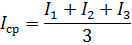
In addition, this creates an asymmetry of the phase voltages, which can lead to damage to consumers' pantographs connected between the phase and neutral conductors. The degree of load unevenness of the transformer phases on the 380/220 V side must not exceed 10%. The degree or coefficient of irregularity ki is determined by the formula

where Imax is the value of the current in the maximum loaded phase, A; Iav — the arithmetic mean value of the currents of all phases at the same time, A:
The total load is checked, the load distribution of voltage levels by phase is carried out at least once a year on a typical day during the periods of maximum and minimum loads of the transformer on the secondary voltage side. An emergency check is performed when significant changes in load occur (connection of new users or increase of capacity of existing ones, etc.).The phase load value is measured on the 0.4 kV side with a clamp meter with an ammeter scale of 5 to 1000 A, and the voltage levels with dial voltmeters with a scale of up to 600 V.