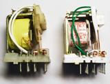
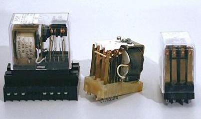
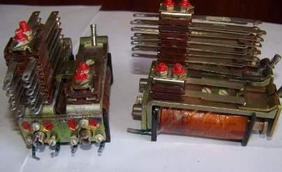
Checking and adjusting the relay during operation
 When switching on again, as well as after rewinding the coils, changing the design or disassembling the relay, the intermediate and indicator relays are checked in the following volume:
a) carry out external and internal inspection and cleaning of the relay,
b) check the condition of the mechanism and relay contacts and, if necessary, adjust them,
c) check the resistance in the dielectric strength of the insulation of live parts to the magnetic circuit,
d) check the operating and return voltage or current, and for a relay with a holding coil, also the current or holding voltage,
e) single-pole coils are specified for multi-coil relays,
f) check the delay time for operation and return for those relays for which this delay is indicated in the selection of settings or is indicated in the instructions for testing protection and automation, which circuit includes the tested relay,
g) check the interaction and reliability of the relay at a reduced voltage of the operating current in the entire protective circuit.
In case of full planned inspections, points a, b, c, f and g are implemented.
In the case of partial regular inspections, as well as additional and special inspections, the scope of inspections is determined depending on the working conditions.

Intermediate and indicator relays do not have special devices for changing their operating current or voltage and the return and delay times. Therefore, these parameters are usually adjusted by changing the value of the initial and final gap between the armature and the core, changing the tension of the return and contact springs, etc. At the same time, the delay time of the relay and the voltage or current change the operation and return at the same time. Therefore, the adjustment of the relay mechanism must be carried out at the same time as checking its electrical characteristics.
During external and internal inspection check:
-
the integrity of the seals,
-
the operability of the casing, its attachment to the base and the seals between the base and the casing,
-
serviceability and quality of glass sealing,
-
the condition of the relay terminals, the serviceability of the threads of the screws and bushings, the integrity of the screw heads and slots, the surfaces of the nuts and the ends of the studs, the presence of washers and locknuts.
Checking the relay mechanism should begin with a thorough cleaning of the relay from dust. It is especially necessary to check the absence of metal chips and shavings on the magnetic circuit, the armature and in the gap between the armature and the core. Dust is removed with a soft brush, sawdust — with a metal plate of a suitable size.
With a slight twitch and inspection, they check the strength of the huskies. Unreliable and oxidized joints are soldered again.The use of acids or soldering compounds is not allowed. Rosin is recommended as a flux. Soldering should be done with POS30 or POS40 solder. Particular attention should be paid to the thorough maintenance of the parts to be soldered before soldering. Soldering must be done quickly, with a well-heated soldering iron, so as not to damage the insulation of the wires when heated strongly.
For relays with flexible multiwire current leads, check for broken wires and breaks in solder joints. In this case, the current wires must be flexible enough, not to interfere with the movement of the mechanism and in any position not to touch the cover of the relay mechanism.
The starting and ending clearances between the armature and the relay core should be of normal value. The clearances are checked by eye. If the electrical characteristics of the relay (operating and reset current or voltage or delay time) deviate from normal values, it is recommended to check the clearances with a pressure gauge.
They check the initial distance between the closing contacts, the deflection of the opening contacts and the closing contacts when closed, check the simultaneity of closing and opening of the contacts.
They check the ease of movement of the relay mechanism, the absence of jamming in each position, the clarity of returning to its original position from each intermediate position.
For relays with axles and bearings, remove the bearings, check the condition of the bearings and the ends of the axles by looking through a magnifying glass.
Contacts that have lost their correct shape are replaced with new ones. Slightly burnt contacts are cleaned with a file and polished.Dented and bent contact springs are straightened or replaced with new ones.
Check the tightness of the screws and nuts securing the parts of the relay and leading to the bushings of the base / plinth. The screws holding the wires inside the relay to the bushing and the screws or studs connecting the outside wires to the relay must not touch each other inside the bushing.
When adjusting the operating and reset current and voltage, delay time, etc., the following basic provisions should be considered:
-
as the initial armature-to-core gap decreases, the response voltage and response delay decrease,
-
as the final armature-to-core gap decreases, the return voltage decreases and the return delay increases,
-
when the return spring is weakened, the response voltage and response delay decrease, as well as the voltage decreases and the return time increases,
-
increasing the number of contact contacts and increasing the pressure of their springs increases the tension and reduces the return time,
-
increasing the number of breaking contacts and their spring pressure increases the response time and voltage.
Using these basic principles, you can choose a convenient way to change its characteristics for each type of relay. It should be borne in mind that all these changes greatly affect the operation of the relay contact system. Weakening of the return spring reduces the reliability of the opening contacts and deteriorates the operation of the closing contacts when the load current is interrupted.Tightening the return spring increases the pressure on the breaking contacts and makes it easier to break the load current with the making contacts.
Therefore, to improve the performance of the contacts, it is advisable to set the maximum possible tension of the return spring, which provides the required voltage or current of operation and the return and delay time. Changing the start and end clearances changes the armature travel and the distance between the fabrication contacts.
Decreasing this distance impairs the reliability of arc interruption from contacts. Therefore, it is more advantageous to have the maximum possible stroke of the armature and, accordingly, the maximum distance between the open contacts.
The parameters of the relay are also affected by the number of working contacts and the tension of the contact springs.
The following sequence of relay tests is recommended:
-
measure and set the distances between the armature and the core, between the contacts recommended by the manufacturers, check the movement of the armature, the possibility of moving the armature in different directions, etc.,
-
check the electrical characteristics of the relay and, if they deviate from normal values, adjust the relay according to the above methods.

