Maintenance of electrical contacts of high voltage electrical equipment
 The contacts of live parts of equipment, connections of equipment, buses, etc. are a weak point in the current-carrying circuit and can become a source of malfunctions and accidents. With this in mind, one should aim to keep the number of contacts as low as possible.
In fig. 1 shows a section of a current-carrying circuit in one of the substations, from which it can be seen that in the section abc there were seven contacts, and after the change there were three. Redundant electrical outlets reducing the reliability of the power supply and may lead to malfunctions and accidents. Therefore, during repair work, it is necessary to provide for the removal of unnecessary contacts from the circuits and the replacement of unreliable contacts with more reliable welded ones.
A number of accidents and malfunctions with contacts occur due to incorrect implementation of contact connections or the use of those that do not meet the requirements of GOST, rules and regulations, as well as unreliable or home-made contacts.The largest number of cases of contact damage occur with rod, transitional (copper - aluminum), bolted and especially single-screw contacts.
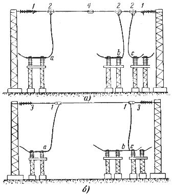
Rice. 1. Diagram of substation section contacts: a — before change, b — after change, 1 — tension clamps, 2 — T-bolt clamps, 3 — steel inserts, 4 — connecting clamp.
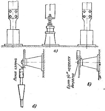
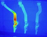
Rice. 2. Some typical cases of contact failure due to their non-compliance with the requirements of the standards: a — the copper core of the insulator is connected to the aluminum bus with a simple nut, b — the cable rod at the break point does not correspond to the cross section of the cable, c — the place where the aluminum busbar is bolted to the copper terminal of the disconnector 400 a …
In fig. 2 shows several typical cases of contact damage. The damage shown in fig. 2, a, occurred on the copper contact of the rod of the middle phase sleeve connected to the flat bus. The two external phases had four-bolt busbar contacts with current transformers, and the contact of the middle rod of the bushing was connected by a common nut to a busbar of the same cross-section as that of the external phases.
The discrepancy between the contact of the middle phase and the contacts of the final phases is obvious. The operating personnel detected overheating of the contact in the middle phase, disassembled and cleaned the contact, but did not take measures to change it, resulting in a major accident.
On the contact (Fig. 2.6) at the cable rod (old type) the cross-section of the place marked by the break line is insufficient in terms of the cross-sectional area of the cable and unreliable in terms of mechanical strength. The destruction of the cable cable on the smallest line led to a major accident.
In fig.3, c shows the inadequacy of the section of 1/4 «bolts used to fasten rather massive busbars to each other and to the disconnectors, the busbars being attached to the disconnectors with a single bolt. As a rule, electrical equipment should be flat. For currents of 200 A and more, flat clamps must have at least two bolts. Operating personnel must identify all contacts that do not meet modern requirements and take measures to eliminate the identified defects.
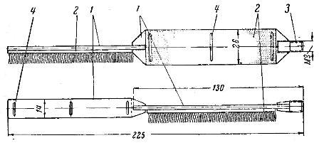
Rice. 3. Manual brush for cleaning the inner walls of oval and tubular connectors of middle sections: 1 — steel plate, 2 — cardo tape, 3 — handle for screwing the handle, 4 — flexible wire for fixing the cardo tape.
During repairs and revisions, the correct and careful installation, cleaning, corrosion protection and installation of removable contact connections are of great importance.
In order to comply with the recommendations for cleaning and lubrication of the contact surfaces and especially of oval or tubular connectors, it is necessary to provide the installer with an installation kit that includes the following items:
1. Brush-brush for cleaning oval, round and flat contact surfaces for connecting wires with a cross section from 25 to 600 mm2 (Fig. 3). The ruffles are wrapped around the handle, which is common for ruffs and brushes of various sizes.
2. A set of plastic jars with petrol, anti-corrosion grease and petroleum jelly.
3. A box in which brushes, cans and rags or rags for cleaning contact surfaces are stored and transported.
Care of soldered contacts
Under normal operating conditions, sintered contacts should operate without stripping until the cermet solder is completely worn away.
The experience of the operation of sintered contacts of high-power high-voltage switches showed that the transient resistance of sintered contacts does not increase after the short-circuit currents are turned off, and even somewhat decreases due to the melting of copper and its leakage to the contact surface.
Cleaning sintered metal contacts with files usually does more harm than good, as the worn contact surfaces of sintered contacts in some cases work better than new ones. Therefore, cleaning the surface of metal-ceramic contacts can be done only if individual frozen lumps of metal are found on the contact surface, which must be removed, after which it is recommended to wipe the contact surface with a cloth soaked in gasoline.
Main indicators characterizing the good condition of the contacts
Electrical contacts are designed so that the transmission resistance of the section of the current-carrying circuit containing the contact is equal to or less than the resistance of the section of the current-carrying circuit of the entire conductor of the same length. The higher the rated current for which the contact is designed, the lower the contact resistance should be.
Contact resistances guaranteed by manufacturers are known for various devices.Over time, the contact resistance of the contacts can increase due to weakening of the contact pressure, formation of hard oxide films that are poor conductors, burning of the contact surfaces, etc.
An increase in the contact resistance of bolted contacts can occur due to the weakening, loosening and violation of contact tightness due to vibration or the difference in the coefficients of thermal expansion of the materials of the bolts and contact rubbers. When the bolts are cooled, increased stresses can form in the contact material, causing plastic deformation of the contact, and with short-circuit currents, rapid heating and expansion of the contact materials occurs, leading to deformation and destruction of the contact.
The lower the contact resistance of the contact, the less heat is released in it when the current passes and the more current can pass through such a contact at a given temperature.
The release of heat in the contact is proportional to the contact resistance and the square of the current: Q = I2Rset, where Q is the heat generated in the contact, Rset — contact resistance, ohm, I — the current passing through the contact, and, t — time , sec.
The measurement of the contact temperature cannot give the desired results if these measurements are not taken during the period of maximum load. From the period In most cases, the maximum loads occur after dark, that is, when the working day ends, it is not possible to measure the contact temperature on the lines and open substations at maximum loads.In addition, the contacts are made more massive than the current-carrying parts, and the thermal capacity and thermal conductivity of the metals are high, so the heating of the contacts does not correspond to the true defectiveness of the contact, determined by the transition resistance. …
In some cases, to evaluate the condition of the contacts, not the value of the contact resistance, but the value of the voltage drop in the section of the current-carrying circuit containing the contact connection is used. The voltage drop will be proportional to the contact resistance and the magnitude of the current: ΔU = RkAz, where ΔU is the voltage drop in the area containing the contact, Rk is the contact resistance, Iz is the current flowing through the contact.
Since the voltage drop depends on the magnitude of the current flowing through the measured section of the current-carrying circuit, the method of comparing the voltage drop in the section of the current-carrying circuit containing the contact and in the section not containing the contact is used to evaluate the condition of the contact.
If, when a current of the same magnitude passes through sections of the same length, the voltage drop in the section containing the contact turns out to be, for example, 2 times greater than the voltage drop in the section of the entire conductor, then, therefore, the resistance in the contact will also be 2 times more.
In this way, the state of contact can be evaluated by three indicators:
a) the ratio of the ohmic resistances of the contact and the entire cross-section of the conductor,
b) the ratio of the voltage drop on the contact and the entire section of the conductor,
(c) the ratio of the temperatures of the contact and the entire conductor.
In some power systems, it is customary to call this ratio the "failure factor".
The contact defect factor K1 is understood as the ratio of the ohmic resistance of the section containing the contact to the ohmic resistance of the section equal to the length of the entire wire: K1 = RDa se/R° С
The contact defect factor K2 is understood as the ratio of the voltage drop in the area containing the contact to the voltage drop in the area equal to the length of the entire conductor at a constant value of the current: K2 = ΔUк /ΔUц
The defect coefficient of the contact K3 is understood as the ratio of the measured temperature in the contact to the temperature of the entire conductor at the same current value: K3 = TYes/T° C
The defect ratio for a good contact is always less than one. When the contact deteriorates, the defect rate increases, and the larger the defect, the greater the defect rate.
Multiple comparative checks of the correctness of rejecting defective contacts were performed by measuring the ohmic resistance of the contact at direct current using a microohmmeter, measuring the voltage drop in the area containing the contact, and measuring the heating temperature of the contact.
At the same time, it was found that the contact defect factor K1 was found to be greater when measuring the transient resistance at direct current than the defect factor K2, obtained by measuring the voltage drop in alternating current at a working load when measuring the temperature of contact heating.Thus, the temperature measurement is not a good indicator of the quality of the contact connection.
The contacts of the power line connectors with a coefficient of defects for resistance or voltage drop above 2, according to the rules for the technical operation of power plants and power transmission networks, are subject to replacement or repair.