Maintenance of switchgear
 The main tasks in the maintenance of the distribution devices (RU) are: ensuring the indicated modes of operation and reliability of the electrical equipment, compliance with the established procedure for carrying out operational switching, monitoring the timely implementation of planned and preventive works.
Reliability of work distribution devices it is common to characterize the specific damage of 100 links. Currently, for a 10 kV switchgear, this indicator is at the level of 0.4. The most unreliable elements of switchgear are actuated circuit breakers (from 40 to 60% of all failures) and disconnectors (from 20 to 42%).
The main causes of failure: failure and overlapping of insulators, overheating of contact connections, failure of drives, failures due to improper actions of service personnel.
The check of the switchgear without disconnection must be carried out:
-
in facilities with permanent staff on duty — at least once every three days,
-
at sites without permanent staff on duty — at least once a month,
-
at transformer stations — at least once every 6 months,
-
Switchgear with voltage up to 1000 V — at least 1 time every 3 months (for KTP — at least 1 time every 2 months),
-
after short-circuiting.
When performing inspections, check:
-
operation of lighting and grounding network,
-
availability of protective equipment,
-
oil level and temperature in oil-filled devices without oil leakage,
-
condition of insulators (dust, cracks, discharges),
-
condition of contacts, integrity of seals of measuring devices and relays,
-
serviceability and correct position of the switch position indicators,
-
operation of the alarm system,
-
operation of heating and ventilation,
-
condition of the premises (serviceability of doors and windows, absence of leaks in the roof, presence and operation of locks).
Extraordinary inspections of open switchgear are carried out in adverse weather conditions — heavy fog, ice, increased contamination of insulators. The results of the inspection are recorded in a special log for taking measures to eliminate the detected defects.
In addition to inspections, equipment and detection devices are subject to preventive checks and tests carried out in accordance with the PPR. The range of activities performed is regulated and includes a number of general operations and some specific work for this type of equipment.
Common include: measuring insulation resistance, checking for heating of bolted contact connections, measuring contact resistance to direct current. Specific checks are timing and movement of moving parts, characteristics of switches, operation of free release mechanism, etc.
Contact connections are one of the most vulnerable points in switchgear. The condition of the contact connections is determined by external inspection and during preventive tests by means of special measurements. During an external examination, attention is paid to the color of their surface, the evaporation of moisture during rain and snow, the presence of luminescence and sparking of the contacts. Preventive tests include checking the heating of bolted contact joints with thermal indicators.
In general, a special thermal film is used, which is red at normal temperature, cherry — at 50 — 60 ° C, dark cherry — at 80 ° C, black — at 100 ° C. At 110 ° C within 1 hour, it collapses and acquires a light yellow color.
A thermal film in the form of circles with a diameter of 10 — 15 mm or strips is glued to a controlled place. In addition, it must be clearly visible to the service personnel.
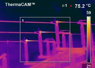
RU 10 kV busbars should not be heated above 70 ° C at an ambient temperature of 25 ° C. Recently, to control the temperature of contact joints, electrothermometers based on thermal resistances, thermal candles, thermal imagers and pyrometers have been used (they work on the principle of using infrared radiation).
The measurement of the contact resistance of the contact connections is carried out for buses with a current of more than 1000 A. The work is carried out on disconnected and grounded equipment using a microohmmeter. In this case, the resistance of the section of the bus at the point of the contact connection should not exceed the resistance of the same section (along the length and cross-section) of the entire bus by more than 1.2 times.
If the contact connection is in unsatisfactory condition, it is repaired, for which it is disassembled, cleaned of oxides and dirt and covered with a special lubricant against corrosion. Retighten with a torque wrench to avoid deformation.
Measurement of insulation resistance is carried out for suspended and supporting insulators with a 2500 V megohmmeter, and for secondary circuits and distribution devices up to 1000 V - with a 1000 V megohmmeter. The insulation is considered normal if the resistance of each insulator is at least 300 megohm, and the insulation resistance of secondary circuits and equipment RU up to 1000 V — not less than 1 MOhm.
In addition to measuring the insulation resistance, the supporting single-element insulators are tested with an increased frequency voltage for 1 min. For low-voltage networks, the test voltage is 1 kV, in 10 kV networks — 42 kV. Control of multi-element insulators is carried out at positive ambient temperature using a dipstick or constant spark gap rod. To reject insulators, special tables are used for the distribution of voltage along the garland. The insulator is rejected if it has less than the allowable voltage.
During operation, a layer of pollution is deposited on the surface of the insulators, which does not pose a danger in dry weather, but becomes conductive in heavy rain, fog, rain, which can lead to overlapping of the insulators. In order to eliminate emergency situations, insulators are periodically cleaned by wiping by hand, using a vacuum cleaner and hollow rods of insulating material with a special tip in the form of curly brushes.
A water jet is used to clean the insulators of open switchgear. To increase the reliability of insulators, their surface is treated with hydrophobic pastes with water-repellent properties.
The main failures of disconnectors are burning and welding of the contact system, malfunction of insulators, drive, etc. driving in other places too.
When adjusting the three-pole disconnectors, check the simultaneous engagement of the blades. With a correctly adjusted disconnector, the blade should not reach the contact pad stop by 3 - 5 mm. The pulling force of the knife from the fixed contact must be 200 N for the disconnector for rated currents 400 … 600 A and 400 N for currents 1000 — 2000 A.
When checking oil switches, insulators, rods, the integrity of the safety valve membrane, the oil level and the color of the thermal films are checked. The oil level must be within the allowable values on the dipstick scale. The quality of the contacts is considered satisfactory if their contact resistance corresponds to the manufacturer's data.
When checking the oil volume switches, attention is paid to the condition of the tops of the contact rods, the integrity of the flexible copper compensators, the porcelain rods. If one or more rods break, the switch is immediately removed for repair.
The abnormal heating temperature of the arcing contacts causes darkening of the oil, increase in its level and a characteristic smell. If the temperature of the tank of the switch exceeds 70 ° C, it is also taken out for repair.
The most damaged elements of oil switches are their drives. Actuator failures occur due to control circuit failures, misalignment of the locking mechanism, malfunctions in moving parts, and breakdown of coil insulation.
The current repair of switchgear is carried out to ensure the operability of the equipment until the next scheduled repair and provides for the restoration or replacement of individual assemblies and parts. Major repairs are being carried out to restore full functionality. It is carried out by replacing any parts, including the main ones.
Current repairs of switchgear with voltages above 1000 V are carried out as necessary (within the time limits set by the chief engineer of the electricity company). Overhaul of oil circuit breakers is carried out 1 time in 6-8 years, load breakers and disconnectors — 1 time in 4 — 8 years, separators and short circuits — 1 time in 2 — 3 years.
Current repair of switchgear with a voltage of up to 1000 V is carried out at least once a year at open transformer substations and after 18 months at closed transformer substations. At the same time, the condition of the end fittings is monitored, cleaning of dust and dirt is carried out, as well as the replacement of insulators, tire repair, tightening of contact connections and other mechanical units, light and sound repair, signal circuits, measurements and tests are carried out , established by the standards.
Overhaul of distribution devices with a voltage of up to 1000 V is carried out at least once every 3 years.
Transferring substations to unmanned switchboard operation frees up highly skilled workers and engineers and technicians from the unproductive labor of keeping records of meter readings and general supervision of the substation. The problem of complete elimination of personnel on duty at switchboards of high-voltage substations is solved by widespread application automation and telemechanics.
In connection with the automation of substations in network areas, the share of centralized repairs carried out by specialized teams has increased sharply. Due to the considerable distance of the substations from each other, it is completely inappropriate to carry out all repairs centrally.