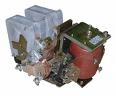
Coils of electrical devices
A coil called a winding of insulated wires, wound on a frame or without a frame, with connecting wires. The frame is made of cardboard or plastic. The coils serve to create a magnetic flux that creates driving forces to operate the apparatus or inductive resistance when the coil is a choke.
Classification of coils of electrical devices
Coils can be divided into two types: current containing a small number of turns of wires with a cross-sectional area corresponding to the strength of the passing current, and voltage coils containing a large number of turns of a small wire.
Coils Apply v contactors for electromagnets.
Isolation coil is overvoltage — voltage spikes when the winding circuit breaks, depending on the speed of the opening of the circuit, the number of turns of its winding, magnetic system of the device. These surges can be transmitted to other relays causing them to operate falsely.
Overvoltage can also be transmitted from an external circuit when the windings of other devices.
Coil voltage
Coils can be produced the same sizes for different voltages — alternating 36, 110, 220, 380, 660 V and constant 6, 12, 24, 36, 48, 60, 110, 220, 440 V. Therefore, the coils of new devices must be checked for compliance with the voltage for which they are made, the mains voltage, which can be done on the label of the complete insulation of the coil winding. The same is done when replacing a failed coil, and if there is no label on the surface of the coil, then it is possible to measure its resistance and compare with the same coil on another apparatus.
 When setting up a new device or changing the coil before fixing it in place, you need to check whether the moving parts of the solenoid touch the coil insulation, and if they do, then you need to place it so that it does not touch, or adjust the movement of moving parts and only then strengthen the coil.
It is necessary to make sure that there is no air gap when touching the armature and the electromagnet core, because if there is an air gap, the inductive resistance of the coil, the current increases and the coil may overheat and go out of order.
When connecting the DC coil, the polarity must be observed when an apparatus such as a polarizing relay responds to the direction of the current.
Overheating coils leads to an increase in the active resistance of the wire, a decrease in the current and a force attracting the core of the electromagnet, which can cause false activation of the relay, an increase in the air gap between the armature of the core, etc. greater overheating of the coil and burning of the insulation of its winding. So you must take care that the coils are not heated by external heat sources such as resistors mounted near and especially below the coil.
Heat coil can be caused by high room temperatures where equipment is installed, high temperature in the control cabinet due to heat emissions from devices, overheating of the device on which the coil is installed. Overheating the device coil can also be with its frequent switching on and shutdown.
High temperature of the coil also leads to a decrease in the insulation resistance of the wire windings. At high temperatures, wire breaks are possible with different thermal expansion of the wire and coil frame. High temperature leads to acceleration of the aging process of the coil insulation.
Moisture can penetrate the coil through the common insulation, insulation between the layers to the wire and help reduce the insulation resistance of the wire. This can cause closure between winding layers or between turns in a layer. As a result of the closure, there may be a break in the wire or shunting of part of the turns, which will contribute to overheating of the coil.
At low temperatures, moisture can freeze in the coil and cause it to malfunction.
Low temperature also contributes to a decrease in the reliability of the coil, because in this case there may be local stresses in the wires and insulation as a result of reducing the volume of materials during cooling.
The windings are affected by mechanical stress in the form of vibration and shock, causing destructive mechanical stresses in the parts of the coil.
V as a result of the influences on the coil, discussed above, the coil may be broken in the current circuit due to breakage of the wire inside the coil, breaks in the wires, oxidation of the terminal clamps, burning of the insulation of part of the turns or complete burning of the insulation on the coil. In the latter case, the coil is said to have burned out.
Coil replacement
Replace the coil is necessary when the wire is broken inside the coil or the turns are closed with various consequences.
When checking the coil after a failure, the complete burnout of its insulation can be seen immediately, because usually the outer insulation of the coil burns out... If the outer insulation is not burned, but the coil does not work, then by bending the outer insulation, you can see the burn wire insulation Checking the opening coil wire can be done with a voltage indicator, ohmmeter, or megohmmeter.
When checking the coil using the voltage indicator with a good winding and the presence of voltage at one terminal of the coil, it should be at the other terminal. This last pin must be disconnected from the mains to eliminate errors when measuring.
 An ohmmeter connected to the terminals of the coil, if the coil is in good condition, it will show its resistance according to the passport, and if there is a closing of the turns, it will show less resistance, but if the closing of the turns occurs only under the action of voltage, the ohmmeter can show no change in resistance.
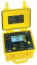
A megohmmeter with a working coil, it will show the resistance of its coil when measured in kilohms slightly more than 0 but less than 1 kOhm, and when measured in megohms - 0, since the resistance of the coil is measured in ohms.