Determination of touch voltage and step voltage during operation of electrical equipment
The contact voltage under operating conditions is determined by the ammeter-voltmeter method. The contact voltage according to this method is measured as the potential difference between the grounded metal parts of equipment or structures accessible to touch and the potential electrode, which is a metal square plate with dimensions of 25 * 25 cm2 imitating the soles of a person standing at a control point on the ground or on the floor.
The resistance of the human body is simulated by the equivalent resistance of a voltmeter U and a resistor connected in parallel R... As a power source of the circuit, an auxiliary transformer is usually used, which is switched on by an electronic short circuit (EKZ) (Fig. 2, a). In the absence of an EKZ, the ammeter-voltmeter method is used with a long-term application of voltage to the tested grounder. In this case, the voltage value is selected from the long-term permissible current passing through the current circuit.
In cases where the secondary winding of the auxiliary transformer has a zero, isolated from the ground or a delta connection, a separating transformer with a secondary voltage of up to 500 V is used (Fig. 2, b).
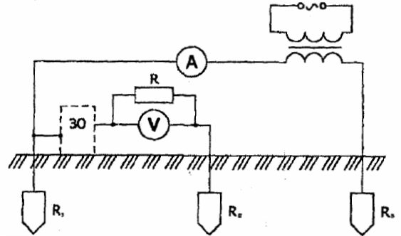
Rice. 1. Scheme for measuring the touch voltage by the ammeter-voltmeter method: Rh — grounding device; ZO grounding equipment; R — resistor simulating the resistance of the human body; Rn — potential electrode (probe); Rv — auxiliary electrode
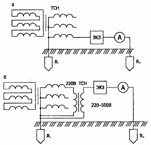
Rice. 2. Circuits of current circuits when measuring touch voltages by the ammeter-voltmeter method: and with the direct use of an auxiliary transformer (TSN); b using an auxiliary transformer (TSN) connected through an isolating transformer
The measured touch voltages are adjusted to the rated earth fault current and to the seasonal conditions under which the touch voltages are most significant.
Un = (Uunit xAzz)(1000 + RHC)/Uunit (1000 +Rn2),
where Umeas is the measured value of the touch voltage at a current in the measuring circuit equal to A unit; 1% calculated for the earthing device, Azh — earth fault current (flowing from the tested earthing device into the ground); Rp resistance of the potential electrode measured according to the scheme shown in fig. 3 and the conditions under which the measurement of Up is performed (dry soil is moistened under the electrode Rn at a depth of 2 — 3 cm); Rp2 is the minimum value of the resistance of the potential electrode, obtained by measuring according to the same scheme, but with artificially moistened soil at a depth of 20 — 30 cm (if during the measurements the soil is moistened at a depth of 30 — 40 cm, then instead of the correction factor 1000 + Rp / 1000 + Rp2 (a coefficient equal to 1.5 is applied).
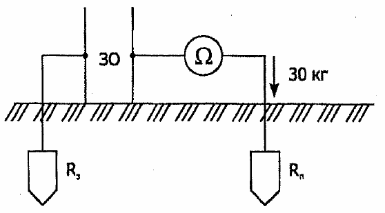
Rice. 3.Scheme for measuring the resistance of a potential electrode
When determining the touch voltage in circuits using an auxiliary transformer, the measuring current can reach too high values. Therefore, measurements in the current circuit must be carried out in the so-called intermittent mode. For this purpose, an electronic short-circuit switch, for example ITK-1, is included in the current circuit, and a pulse voltmeter is used as a voltage meter (see Fig. 2).
In addition to the ammeter-voltmeter method, the voltage during standstill can be measured with special devices - the so-called «touch measuring devices».
The step voltage can be determined by the ammeter-voltmeter method using a welding transformer (Fig. 4).
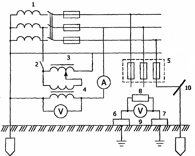
Rice. 4. Step circuit for voltage measurement with two voltmeters and an ammeter using a welding transformer: 1 — substation transformer; 2 — unipolar switch; 3 — autotransformer; 4 — welding transformer; 5 power distribution cabinet; 6, 7 — measuring plates; 8 — resistor; 9 — transistor voltmeter; 10 — metal structure
The measuring circuit contains two potential electrodes, which are metal square plates 25×25 cm2 each. The plates mimic the soles of a person standing on the ground or floor. The distance between the plates should correspond to the calculated human step, equal to 0.8 m. The surface of the ground at the calculated points is moistened to a depth of 2 — 3 cm. For better contact with the ground, a load weighing at least 50 kg is placed on each plate.
The step voltage is determined by the formula:
Uw = (Unn xUe) /UT
where Unn — voltage measured with a voltmeter between two plates, V; Ue- phase voltage of the network, V; UT — voltage on the secondary winding of the welding transformer.