DC electromagnetic contactors
DC contactors are designed to switch DC circuits and are typically driven by a DC electromagnet.
General technical requirements for contactors and their operating conditions are regulated by GOST 11206-77. The application categories of modern contactors are described below and the parameters of the circuits they switch are given, depending on the nature of the load.
DC contactors:
DS-1-active or low inductive load.
DC-2-starting DC motors with parallel excitation and their shutdown at rated speed.
DS-3-starting of electric motors with parallel excitation and their shutdown in a stationary state or slow rotation of the rotor.
DS-4-starting of electric motors with series excitation and their shutdown at rated speed.
DS-5-starting of electric motors with series excitation, shutdown of stationary or slowly rotating motors, counter current braking.
General requirements for contactors:
1. High productivity and interruption — not less than 10Inom, and in some cases up to 20Inom;
2. Long-term operation at high cut-off frequency;
3. High duration of switching — up to 3 million cycles, taking into account interruptions of starting currents;
4. High mechanical durability;
5. Design performance, low weight and dimensions;
6. High operational reliability.
For contactors, there is also a mode of rare commutations, characterized by more severe conditions than in normal commutations. Such modes occur quite rarely (for example, when short circuits).
The main technical data of the contactors are the rated current of the main contacts, the limiting breaking current, the rated voltage of the connected circuit, the mechanical and switching endurance, the permissible number of starts per hour and the own on and off time. The ability of the contactor, like any switching device, to provide operation with a large number of operations is characterized by wear resistance.
 Distinguish between mechanical and switching wear resistance. Mechanical durability of contactors is determined by the number of contactor on-off cycles without repair and replacement of its assemblies and parts. In this case, the current in the circuit is zero. Mechanical durability of modern direct current contactors is (10-20) 106 operations.
The switching life of the contactors is determined by the number of times the circuit is switched on and off after which the contacts need to be replaced. Modern contactors should have a switching endurance on the order of (2-3) 106 operations (some contactors currently in production have a switching endurance of 106 operations or less).
The intrinsic closing time of the contactor consists of the rise time of the flux in the contactor solenoid to the starting flux value and the armature travel time. Most of this time is spent building up the magnetic flux. For DC contactors with a rated current of 100 A, the inherent switching time is 0.14 s, for contactors with a current of 630 A it increases to 0.37 s.
Intrinsic contactor opening time — the time from the moment the contactor solenoid is turned off until its contacts open. It is determined by the decay time of the flux from the steady state value to the decaying flux. The time from the start of armature movement to the moment the contacts open can be neglected. For DC contactors with a rated current of 100 A, the inherent breaking time is 0.07, for contactors with a rated current of 630 A — 0.23 s.
Rated current of the contactor Inom is a current that can pass through the closed main contacts for 8 hours without switching, and the temperature rise of various parts of the contactor should not exceed the permissible value (periodic-continuous operation).
A contactor's rated operating current Inom.r is the allowable current through its closed main contacts in a specific application. So, for example, the nominal operating current Inom.r. of the switching contactor of squirrel-cage rotor induction motors is selected from the switch-on conditions six times the starting current of the motor.
Contactor rated voltage is the highest switched circuit voltage for which the contactor is designed to operate.
Switching durability of the main contacts for categories DS-2, DS-4 in normal switching mode, it should be at least 0.1, and for categories DS-3, at least 0.02 mechanical durability.
Auxiliary contacts must switch circuits of alternating current electromagnets, in which the inrush current can be many times higher than the stationary one.
A DC contactor has the following main components: a contact system, an arc extinguishing device, an electromagnet and an auxiliary contact system. When voltage is applied to the coil of the contactor's electromagnet, its armature is attracted. A movable contact connected to the armature of the electromagnet makes or breaks the main circuit. The arc extinguishing device ensures rapid arc extinguishing, resulting in low contact wear. The system of auxiliary low-current contacts serves to coordinate the operation of the contactor with other devices.
Contact system of DC contactors. The contacts of the device are subjected to the heaviest electrical and mechanical wear due to the large number of operations per hour and the harsh working conditions. To reduce wear, linear rolling contacts prevail.
To prevent contact vibrations, the contact spring creates a pre-pressure equal to about half of the final contact force. Vibration is strongly influenced by the stiffness of the stationary contact and the vibration resistance of the entire contactor as a whole. In this regard, the construction is very successful contactor series KPV-600.
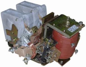
The KPV-600 series DC contactor device
The fixed contact 1 is firmly attached to the bracket 2. One end of the arc extinguishing coil 3 is attached to the same bracket.The second end of the coil, together with the wire 4, is firmly attached to an insulating base made of plastic 5. The latter is attached to a strong steel bracket 6, which is the base of the apparatus. The movable contact 7 is made in the form of a thick plate.
The lower end of the plate has the ability to rotate relative to the pivot point 8. Therefore, the plate can be overturned through the cradle of the fixed contact 1. Lead 9 is connected to the movable contact 7 by means of a flexible wire (link) 10. The contact pressure is created by the spring 12.
When the contacts are worn, the cracker 1 is replaced with a new one, and the movable contact plate is rotated 180 ° and its undamaged side is used in operation.
To reduce the melting of the main contacts from the arc at currents above 50 A, the contactor has arcing contacts — horns 2, 11. Under the action of the magnetic field of the arc extinguishing device, the reference points of the arc are quickly moved to the clamp 2 connected to the fixed contact 1, and to the protective horn of the movable contact 11. The armature is returned to its original position (after the magnet is turned off) by the spring 13.
The main parameter of the contactor is the nominal current, which determines the dimensions of the contactor.
A characteristic feature of contactors KPV-600 and many other types is electrical connection of the movable contact of the output to the body of the contactor.
In the on position of the contactor, the magnetic circuit is energized. Even in the off position, voltage may remain on the magnetic circuit and other parts. Therefore contact with the magnetic circuit of the contactor is life-threatening !!!
The KPV series contactors have an NC contact design.The closing is done due to the action of a spring, and the opening is due to the force developed by an electromagnet.
 Rated current of the contactor called current of intermittent-continuous operation. In this operating mode, the contactor remains on for no more than 8 hours. After this interval has elapsed, the device must be turned on and off several times (to clean the contacts from copper oxide). Then the device turns on again.
If the contactor is placed in a cabinet, the rated current is reduced by about 10% due to deterioration of the cooling conditions. V
continuous operation, when the duration of continuous switching is more than 8 hours, the allowable current of the contactor is reduced by about 20%. In this mode, due to the oxidation of copper contacts, the contact resistance increases, which can lead to an increase in temperature above the permissible value.
If the contactor has a small number of switches or is usually intended for continuous switching, then a silver plate is soldered on the working surface of the contacts. The silver lining keeps the allowable current of the contactor equal to the rated current even in continuous operation.
If the contactor, together with the continuous switching mode, is used in the intermittent switching mode, the use of silver linings becomes impractical, because due to the low mechanical strength of silver, the contacts quickly wear out.
According to the recommendations of the plant, the permissible interrupting current for the KPV-600 contactor is determined by the formula:
, where n is the number of starts per hour.
It should be noted that if the arc burns for a long time with periodic shutdown (shutdown of a large inductive load), the temperature of the contacts may increase sharply due to the heating of the contacts by the arc. In this case, the heating of the contacts during continuous operation may be less than during intermittent operation. As a rule, the contact system has one pole.
It is used to reverse asynchronous motors at a high starting frequency per hour (up to 1200) double contact system... In these KTPV-500 permanent magnet type contactors, the movable contacts are isolated from the housing, which makes it safer to service the device.
The figure shows the circuit for switching contactors for reversing asynchronous motors. Compared to a circuit with single-pole contactors, this scheme has a great advantage. In case of faults and failure of one contactor, the voltage is applied to only one terminal of the motor. With single-pole contactors, failure of one contactor will result in heavy-duty two-phase motor supply.
Connection diagram of the main contacts of the contactor KTPV-500 for reversing an asynchronous motor.
Contactors with a two-pole contact system are very convenient to use for short-circuit resistances in the rotor circuit of an induction motor.
In KMV-521 type contactors, a two-pole system is also used. These contactors are designed for switching on and off powerful electromagnets of DC drives for oil circuit breakers... The presence of a two-pole contact system included in the two wires of the DC network ensures reliable switching off of the inductive load.