Devices for locating faults on overhead power lines
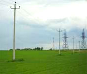
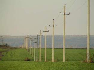
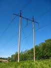 In electrical networks, devices for determining the places of failure are widespread, mainly on overhead power lines voltage of 10 kV and more, based on the measurement of emergency mode parameters. These devices can be divided into two main groups, designed to locate places of damage in case of short circuit and grounding.
Determining the fault locations in the event of a short circuit
Determining the location of a short-circuit on the lines is particularly important, since the interruption of the line in case of permanent damage is associated with undersupply of electricity and material damage to consumers. In these cases, expediting the search for damages has a large economic effect.
Devices to accelerate the search and determine the location of short circuits according to the principle of operation, it can be divided into two subgroups:
1) fixing devices for determining the distance to the place of damage, automatic measurement and fixing of the relevant electrical quantities during emergency operation;
2) devices for determining damaged sections of lines (network sensors, short-circuit indicators, automatic monitoring and fixing of changes in electrical values during emergency operation).
Various types of fixation devices have been developed, a number of which are in successful operation. In rural distribution networks with a voltage of 10 kV, devices of the FIP type (FIP-1, FIP-2, FIP-F), LIFP, etc. are used. The FMK-10 type device is also widely used.
 Given that the fixing devices provide automatic measurement and fixing of electrical quantities during a short circuit, they must meet certain requirements, in particular the following: the measurement must be completed before disconnecting the damaged sections of the line from the relay protection, that is, within about 0.1 s, the device must maintain the value of the fixed electrical quantity for a time sufficient for the arrival at the substation (without permanent duty) of the operational field team, i.e. not less than 4 hours, automatic selective start of the devices should be provided, so that the observed value is fixed only in case of emergency stops of the lines, the device should provide a certain measurement accuracy (usually the relative measurement error should not to exceed 5%) etc.
One of the simplest options for fixing devices — a short-circuit current measuring device... Moreover, to determine the distance to the short-circuit location, you can solve the problem, the opposite of what is taken into account when calculating the current of short-circuit, and the known values of current and voltage of short-circuit resistance to the point of short-circuit must be accurately determined. Knowing this resistance, it is not difficult to, with known network parameters, find the distance to the short circuit point.
The most common are fixing devices with so-called electrical memory... They are based on the use of a storage capacitor. Moreover, during a short-circuit process, the storage capacitor is rapidly charged to a voltage proportional to the value of the detected short-circuit current (or corresponding voltage). Then, in the next step, the reader is connected to the storage capacitor that controls the long-term memory element. In this way, the above requirements for fast measurement are ensured before the line is turned off under the action of relay protection and the ability to maintain a fixed value for a long time.
On this principle, the above devices of the FIP type were developed, which found application in rural 10 kV networks.
To facilitate the practical use of devices that are fixed short-circuit current, so that it is not necessary to perform calculations every time at emergency, equilibrium current curves.At the same time, the short-circuit currents are calculated in advance for a sufficiently large number of points on each output line, and according to the calculation results, an equivalent current is applied to the line circuit. curves of the main part of the line and branches with equal values of short-circuit currents. After the device fixes certain short circuit current value, according to the line diagram with equinox current curves, it directly determines the fault search area.
The simplest devices of the FIP type, however, record the current of short-circuits have a number of disadvantages, including the following: to determine the distance to the short-circuit point, additional calculations or preliminary construction of equal current curves, the accuracy of measurement (instrument error) is affected from the contact resistance at the fault location (primarily the arc resistance), the network voltage level, the value of the load current (the device actually measures the total load and short-circuit current), etc.
Clamping ohmmeters are more perfect, especially those that measure reactance. When measuring resistance, that is, the ratio of voltage to current, it is possible to significantly reduce the effect of changing voltage levels on the accuracy of the measurement. The measurement of reactance also reduces the effect of arc resistance at a short-circuit point, which is mostly active, and enables the completion of an instrumented scale in kilometers. If, in addition, the devices measure the load current preceding the short-circuit mode, it becomes possible to take into account and accordingly reduce the influence of the load current.
An ohmmeter, unlike clamping ammeters and voltmeters, measures not one, but two quantities (current and voltage) that are fed to its input. To reduce the shunting effect of the load, it can be measured separately load current preceding the occurrence of a short circuit. All these values are fixed (remembered) according to the principle discussed above (in this case, the currents are pre-converted into voltages proportional to them), and then, using special circuits (conversion blocks), they are converted into signals proportional to the resistance (total, reactive, taking into account the current of the previous load) etc.). Given that the reactive (inductive) resistance of the lines depends little on the cross-sectional area of the wires used, the scales of these devices are graduated in kilometers. Such devices include fixing ohmmeters such as FMK-10, FIS, etc.
Devices for detecting damaged overhead lines
 With the help of such devices, you can determine the direction of search for short-circuit points on overhead lines with a voltage of 10 — 35 kV. The devices, as a rule, are installed in the line branch — on the first support after the connection point. They record the occurrence of a short-circuit when it occurs on a branch or section of the main line for the point of installation of the device. When searching for a short circuit on the broken line, they receive information from these devices about the presence (the device is triggered) or absence (not working) of a short circuit behind the place of its installation.In electrical networks, indicators for damaged areas of the UPU-1 type and more advanced and reliable short-circuit indicators of the UKZ type are widely distributed.
The indicator fixes the occurrence of a short circuit when using a magnetic (induction) current sensor installed in the area of wires, but without direct connection to them. One indicator provides information about all types of phase-phase short circuits.
The indicator of the UKZ type is made in the form of an executive unit containing, in addition to the magnetic sensor, an electronic control circuit and a magnetic indicator.
If a short circuit occurs behind the installation site It is triggered by the short circuit inrush current, as a result of which the indicator flag turns to the observer with a side painted in bright orange color and remains in this position if the line is interrupted by the protection.
After activation of the line (upon successful automatic closing or after the fault has been removed), the indicator flag automatically returns to its original position. The return of the flag is due to the capacitive selection of the grid voltage using the antenna converter.
The installation of signs enables service personnel if the line is damaged, personnel bypass the branch points and after determining a damaged area, bypass to find only the short-circuited damaged area, not the entire line. It is recommended to set pointers both in the absence and in the presence of fixing devices to determine the distance to the short circuit point.In the second case, pointers are accelerated search due to the fact that due to the branching of rural lines 10 kV readings fixing devices determine not one, but, as a rule, several short circuit points (on the trunk and various branches).
Devices for determining the location of a single-phase short circuit to earth
Single-phase earth faults are the most common type of fault. In rural 10 kV distribution networks operating with an isolated neutral, single-phase earth faults accompanied by relatively low currents are not short circuits. Therefore, when they occur, it is allowed not to turn off the line for the time necessary to repair the fault.
However, it is necessary to locate and repair faults as quickly as possible, as a single-phase earth fault can become a double-phase one. The latter is a short circuit and will be disabled by protection, resulting in a power cut to users.
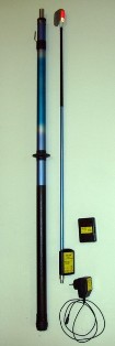
In addition, ground damage is possible, for example, when a wire breaks and falls to the ground, which are very dangerous for the lives of people and animals. At the same time, ground faults can occur as a result of hidden damage, for example due to internal cracked insulatorswhen there are no external signs of a short circuit and it is very difficult to detect visually. Therefore, special devices have been developed - portable devices that make it easier and faster to find the place of damage.
The principle of operation of portable devices used in electrical networks with a voltage of 10 kV, based on the measurement of the higher harmonic components of the earth fault current.The significantly higher level of harmonics in the spectrum of earth fault currents compared to load currents ensures efficient operation of these devices.
In rural electrical networks of 10 kV, devices of the type "Search" (discontinued) and more advanced "Wave" and "Probe". In the "Search" and "Wave" devices, the main elements are a magnetic (inductive) sensor that detects the appearance (amplitude increase) of harmonic components of the current, a filter with higher harmonics that passes those of them for which the device is configured , the amplifier provides the necessary signal gain and a measuring device that produces the resulting signal.
The location of the earth fault in the line is determined as follows. If the line bypass starts at the substation, measurements are made at the line outlet from the substation, placing the device under the line. The broken line is determined by the maximum deviation of the needle of the measuring device. By taking measurements at the branching points of the damaged line, the damaged branch or section of the trunk is determined in the same way. Behind the location of the ground fault, the readings of the device decrease sharply, which determines the point of failure.
The «Probe» device is a directional device, that is, it provides not only the determination of the location of the earth fault, but also the direction of search, which is of interest if the search starts not from the substation, but from some point of the damaged line. Its operation is based on a comparison of the voltage and current phases of the 11th harmonic (550 Hz).Therefore, in addition to the indicated basic elements, the "Probe" has a phase comparison organ, and the output measuring device has a scale with zero in the middle.