Methods for determining the locations of damage to cable lines
 In the event of a cable line fault, the fault zone is determined in advance, then the location of the fault is determined and identified using, depending on the nature of the fault, induction, acoustic, contour, capacitive, pulse or oscillatory methods discharge (Figs. 1 and 2).
Induction method (see Fig. 1, a) is used in case of insulation breakdown between two or three wires of the cable and low transition resistance at the location of the damage. The method is based on the principle of capturing a signal on the earth's surface when a current of 15–20 A with a frequency of 800–1000 Hz passes through the cable. When listening to the cable, a sound is heard (the loudest is above the location of the damage and sharply decreases behind the location of the damage).
For search, a device of the type KI-2M and others is used, a lamp generator 1000 Hz with an output power of 20 VA (type VG-2) for cables up to 0.5 km long, a machine generator (type GIS-2 ) 1000 Hz, with a power of 3 kVA (for cables up to 10 km).The induction method also determines the route of the cable line, the depth of the cable and the location of the connectors.
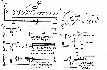
Rice. 1. Methods (diagrams) for determining the location of a cable line fault: a — induction, b — acoustic, c — loop, d — capacitive
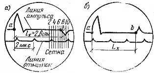
Rice. 2. The image on the screen of the ICL device at the place of damage in the cable line: a — with a short circuit of the cable cores, b — with a break in the cable cores.
An acoustic method (see Fig. 1, b) is used to determine directly on the track the location of all types of damage on the cable line, provided that a sound boom is created at this location, which is perceived on the earth's surface using an acoustic device. In order to create an electrical discharge at the location of a cable fault, there must be a through hole formed by the burning of the cable from a gas turbine plant, as well as sufficient transition resistance to form a spark discharge. Spark discharges are created by a pulse generator and are perceived by a sound vibration receiver such as AIP-3, AIP-Zm, etc.
A feedback method (see Fig. 1, c) is used in cases where a core with damaged insulation does not have a break, one of the intact cores has good insulation, and the value of the transient resistance at the point of damage does not exceed 5 kOhm. If it is necessary to reduce the value of the transient resistance, the insulation is burned with a kenotron or a gas pipe installation. The circuit is powered by a battery, and with high transient resistances by a BAS-60 or BAS-80 dry battery.To determine the location of the fault, an undamaged core is connected to the damaged one at one end of the cable, and at the other end a measuring bridge with a galvanometer powered by a battery or battery is connected to these cores. Balancing the bridge, the location of the failure is determined using the formula
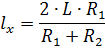
where Lx is the distance from the place of measurement to the place of damage, m, L - the length of the cable line (if the line consists of cables of different cross-sections, the length is reduced to one cross-section equivalent to the cross-section of the largest segment from the cable), m, R1, R2 — resistance of the arms of the bridge, Ohm.
The deviation of the arrow of the device in the opposite direction when changing the ends of the wires connecting the device to the core indicates that the fault is located at the very beginning of the cable on the side of the measurement point.
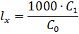
Capacitive method (see Fig. 1, d) determine the distance to the place of failure when the cable cores are broken in the connectors. When a core is broken, its capacity is measured C1 first from one end and then the container C2 same core from the other end, then the length of the cable is divided in proportion to the resulting capacitances and the distance to the fault location lx is determined using the formula

When solidly grounding a damaged core, the capacitance of one section and of the entire core is measured from one end, and then the distance to the location of the fault is determined by the formula

If the capacitance C1 of the broken core can only be measured from one end, and the other cores have solid ground, then the distance to the fault location can be determined by the formula
where B.o — specific capacitance of a conductor for a given cable, taken from the tables of cable characteristics.
For measuring by the capacitive method, generators with a frequency of 1000 Hz and bridges are used: direct current (only with a clean break in the wires) and alternating current (with clean breaks in the wires and with transient resistances of 5 kΩ and higher).
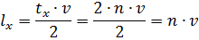
Pulse method (see fig. 2) determine the location and nature of the damage. The method is based on the measurement of the time interval by the ICL device Tx, μs, between the moment of application of the pulse and the arrival of its reflection, determined by the equality

where n — the number of scale marks on the screen of the ICL device,
° C —scale separation value is equal to 2 μs.
Distance lx from the beginning of the line to the location of the fault is established by taking the propagation speed v of the pulse along the cable equal to 160 m / μs, according to the formula
Oscillating discharge method It is used to detect "floating" insulation tears that occur in cable bushings due to the formation of cavities in them during the test, which play the role of spark gaps. To determine the location of damage, the voltage from the kenotron installation is applied to the damaged core, and according to the readings of the device (EMKS-58, etc.), the distance to the location of the damage is determined.