Phase shift transformers and their use
 In AC networks, the active power flows in the lines are proportional to the sine of the phase shift angle between the voltage vectors of the source of electrical energy located at the beginning of the line and the sink of electrical energy located at the end of the line.
So, if we consider a network of lines that differ in transmitted power, then it is possible to redistribute the power flows between the lines of this network, in particular changing the value of the phase shift angle between the source voltage vectors and the receiver in one or more lines of the considered three-phase network.
This is done to load the lines in the most favorable way, which is often not the case in normal cases. The natural distribution of energy flows is such that it leads to overloading of low-power lines, while energy losses increase and the capacity of high-power lines is limited. Other consequences detrimental to electrical infrastructure are also possible.
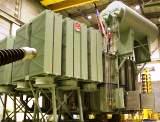
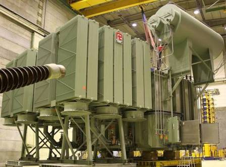
A forced, purposeful change in the value of the phase shift angle between the source voltage vector and the receiver voltage vector is carried out by an auxiliary device — a phase-switching transformer.
In the literature there are names: phase-switching transformer or crossover transformer... This is a transformer with a special design and is intended directly for controlling currents, both active and reactive power in three-phase AC networks of different sizes.
The main advantage of the phase-shifting transformer is that, in the maximum load mode, it can unload the most loaded line, redistributing the power flows in an optimal way.

A phase-shift transformer includes two separate transformers: a series transformer and a parallel transformer. The parallel transformer has a primary winding made according to the "delta" scheme, which is necessary to organize a system of three-phase voltages with an offset relative to the phase voltages by 90 degrees, and a secondary winding, which can be made in the form of isolated phases with a drain block with ground center.
The phases of the secondary winding of the parallel transformer are connected through the tap-changer output to the primary winding of the series transformer, which is usually in star arrangement with the neutral grounded.
The secondary winding of the series transformer, in turn, is made in the form of three isolated phases, each connected in series in the section of the corresponding linear conductor, correlated in phase, so that a component that is phase-shifted by 90 degrees is added to the voltage vector of the source.
So, at the output of the line, a voltage equal to the sum of the supply voltage vectors and the additional vector of the quadrature component, which is introduced by the phase-shifting transformer, is obtained, that is, as a result, the phase changes.
The amplitude and polarity of the introduced quadrature component, which is created by the phase-shifting transformer, can be changed; for this, the possibility of adjusting the block of taps is provided. Thus, the angle of phase shift between the voltage vectors at the input of the line and at its output is changed by the required value, which is related to the operating mode of a certain line.
The costs of installing phase-shifting transformers are quite high, but the costs are paid off by optimizing the operating conditions of the network. This is especially true for high power transmission lines.
In Great Britain, phase-shifting transformers began to be used as early as 1969, in France they have been installed since 1998, since 2002 they have been introduced in the Netherlands and Germany, in 2009 — in Belgium and Kazakhstan.
Not a single phase transformer has been installed in Russia yet, but there are projects. The world experience with the use of phase-shifting transformers in these countries clearly shows an improvement in the efficiency of electrical networks thanks to the management of energy flows with the help of phase-shifting transformers for optimal distribution.