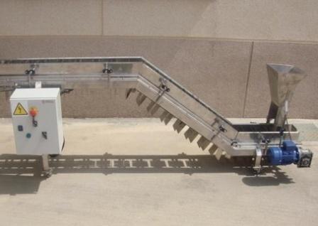
Layout of a conveyor line with three conveyors
 When managing a group of conveyors serving a complex technological complex, it is necessary to introduce various interlocks. In addition, signaling the state of the mechanisms is very important in the design of the control circuit, which is most often implemented using a lightweight mnemonic circuit located on the operator control panel.
In fig. 1 shows a conveyor line consisting of three consecutive conveyors. The electrical drive of the belt conveyors is provided by squirrel-cage rotor asynchronous motors, the control circuit of which is shown in the same figure.
The control circuit of the electric motors of the conveyor group provides: the necessary duration of starting the conveyor line in the direction opposite to the load flow. This eliminates the danger of clogging the overload point. Therefore, the start of each subsequent conveyor (in the direction against the flow of goods) is allowed only when the load-bearing body of the previous conveyor is fully accelerated.
This blocking is done using a speed relay that controls the movement of the traction element; the necessary sequence of stopping the conveyor line in the direction of the load flow.
Such interlocking shall be provided as to ensure, in the event of an emergency stop of one of the conveyors, the stopping of all conveyors from the loading point to the stopped conveyor, and the remaining conveyors shall continue to operate in order to release the towing body from the load; control of the start time of the belt conveyors.
Prolonged starting indicates either a malfunction of the electric motor or its control system, or slippage of the belt on the drive drum, which is unacceptable.
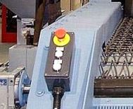
The control circuit must provide the possibility of stopping the conveyor line from any point, emergency stop of the conveyor and all subsequent ones in the direction of start in case of: extended time of starting the conveyor, reduction of the speed of the conveyor belt, breakage of the traction element, unacceptable exceeding the speed of movement of the traction element, overloading the electric motor of the conveyor, overheating of the bearings of the driving drums, the formation of blockages in the places of overloading, lowering of the conveyor belt, the intrinsic safety of the control circuits and the minimum number of cores.
The following types of signaling must be provided in the control scheme of the flow-transport system: warning, emergency, for the number of connected conveyors, etc.
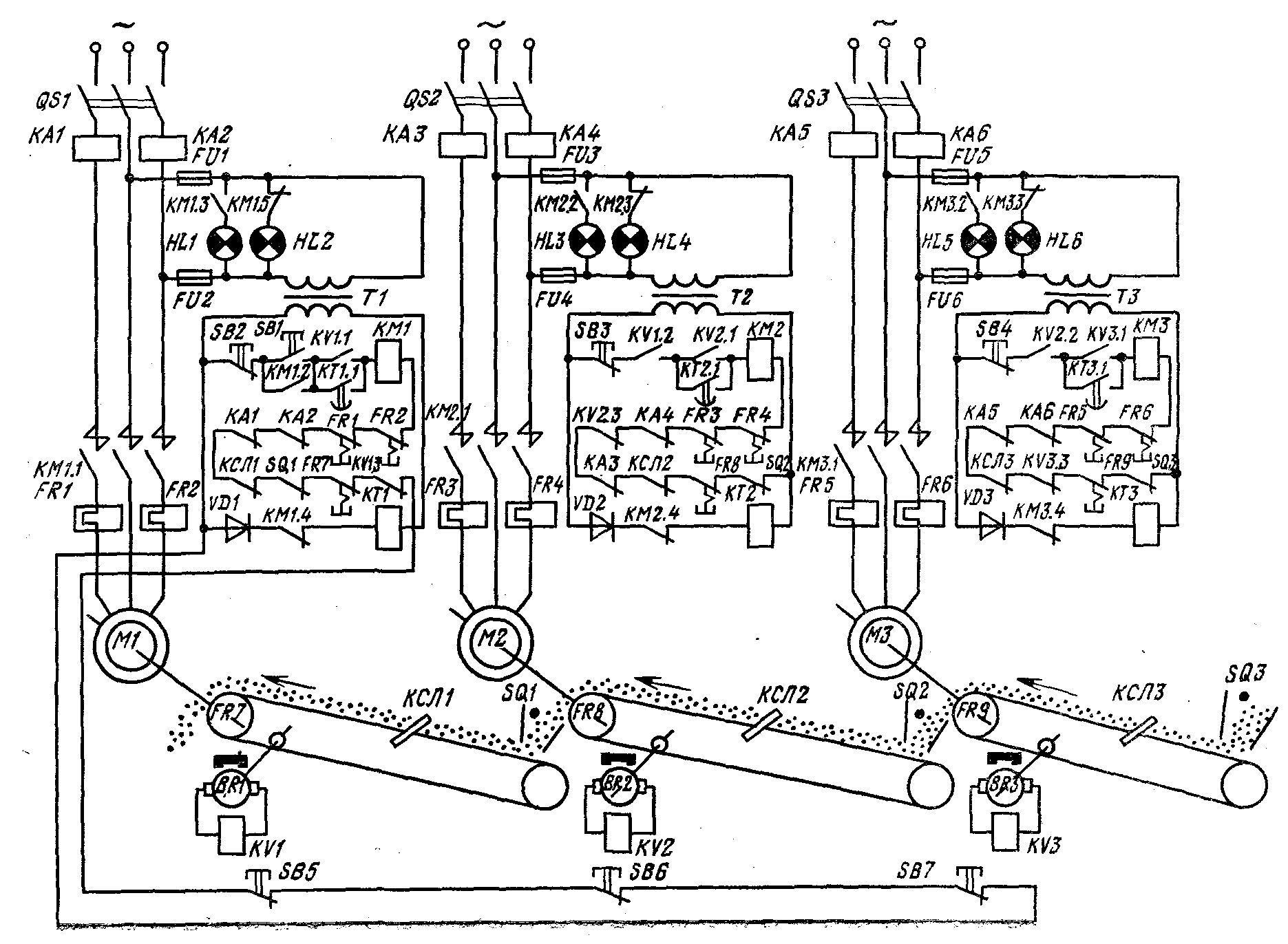
Rice. 1. Control circuit of the electric drive of three conveyors (flow conveying system)
According to the above requirements, the start of the conveyor line is carried out in the following sequence.First, the M1 motor is started by pressing the SB1 button. At the same time, contactor KM1 receives power and, when actuated, closes its line contacts KM1.1 in the stator circuit of asynchronous motor M1. The motor starts rotating, driving the conveyor belt.
At the same time, the auxiliary contacts are closed: KM1.2, which bypasses the SB1 button, and KM1.3, which turns on the signal lamp HL1, indicating the operating state of the motor M1. Opening contact KM1.4 turns off time relay KT1, which counts the time required to accelerate the motor to its maximum speed.
 When the conveyor belt is in motion, the shaft of the tachogenerator of the speed relay KV1 rotates. When the conveyor belt reaches its maximum speed, the relay KV1 gives a signal to close its contacts: KV1.1 in the circuit, bypassing the contact KT1.1, and the second — KV1.2 in the control circuit of the next conveyor.
The normal course of the starting process is controlled by the time relay KT1. After the set time has elapsed, relay KT1 releases its armature and causes its contact KT1.1 to open in the contactor circuit KM1. Despite the opening of contact KT1.1, contactor KM1 continues to receive power through the closed contact KV1.2.
If for some reason the belt has not reached its maximum speed during the time required to start, the contact KT1.1 will open before the contact KV1.1 closes, and the motor M1 will stop because the circuit of the contactor KM1 will be open .
The tightening is caused by the belt slipping over the drum. This is a dangerous mode that can cause the tape to catch fire. Therefore, the circuit provides an interlock that turns off this dangerous mode.In the case of a normal start of the first motor M1, a signal is given to turn on the motor M2 of the second conveyor — contact KV1.2 closes. The coil of the contactor KM2 flows around with current and when actuated closes its contacts KM2.1 in the stator circuit of the second motor M2. Control over the start of the second engine is carried out in the same sequence.
The following types of protection are provided in the electric motor control schemes:
-
from motor overload — thermal relays FR1 — FR6;
-
from overheating of the drive drum bearings — thermal relays FR7 — FR9;
-
from overspeed of the conveyor belt — speed relay KV1.3 — KV3.3;
-
from the descending band — relay KSL1 — KSL3;
-
from blocking at the charging points — through switches SQ1 — SQ3.
When one of the types of protection is triggered, not only the conveyor that has an accident stops, but also the following ones against the flow of the load. The remaining conveyors in the direction of the load flow remain operational.
In the control circuit, light signaling is applied, which shows the status of the electric motors: green lamps HL2, HL4, HL6 are on, indicating the deactivated state of the motor, red HL1, HL3, HL5 — for working state. You can stop the conveyor line from any point on the track by pressing one of the buttons SB5, SB6, SB7.