Electric drive control circuits
 Depending on the speed of passenger elevators, the following types of power control circuits are accepted:
-
low-speed elevators have squirrel cage or phase rotor motors and a button or lever control,
-
high-speed elevators-two or one-speed motors controlled by magnetic stations or thyristor control stations (TSU-R) with control buttons,
-
high-speed and high-speed elevators - DC motors controlled by the "generator - motor" system with different excitation schemes or by the "thyristor converter - motor" system with buttons,
-
chains of asynchronous valve cascades (AVK) can also be used, the use of which makes it possible to increase efficiency. installation.
Passenger elevators, depending on passenger flow, lifting height and the number of elevators serving passengers, are divided into single and group control.
Singles include:
a) elevators operating on single orders and calls without crossing stops during the descent and ascent of passengers,
b) elevators with boarding of passengers when going down, but with a ban on calls when going up,
c) the same, but with registration of calls when descending with their subsequent execution.
Group operated elevators include:
a) elevators with one button for calling the landing places, regardless of the number of installed elevators (double control is more often used) and with passenger boarding when descending,
b) the same, but with the complete collection of passengers on the intermediate floors for boarding and disembarking (usually installed in administrative, educational and other buildings).
In addition, it is very common to send elevators to a number of houses and entire neighborhoods, when the state of the circuits is monitored from one dispatch console and several elevators are controlled.
Regardless of the speed of the elevators, single or group control of them, the necessary elements of most of their schemes are as follows:
-
self-adjusting buttons, sticky or closing buttons for calling cabs and giving an order from the cab,
-
various selection sensors and precise stop matching devices to register the location of the cabin and the state of the electrical circuits,
-
sensors and interlocks for the state of the hoisting ropes, the state of the mine and cabin doors (open or closed),
-
limit switches to limit the speed and degree of cabin load,
-
indicators for the direction of movement of the car and, in some elevators, the presence of a load in the car.
Of these items, we will dwell in more detail on position matching devices (PSCs), which determine the place where the mine car must stop when a call or order occurs, and its movement up or down.The remaining items are usually various modifications of limit switches known from other courses.
Structurally, position matching devices are implemented in the form of a set of three-position electromechanical or inductive or magnetic (reed) sensors located in mines, with signals output to a relay or non-contact selector in the engine room (CCPs are sometimes implemented in the form of central floor units located in the engine room) …
The sensors located in the mine interact with the cab-mounted branches (for electromechanical) or magnetic shunts (for inductive or reed switches) and send signals to the central floor unit (step copier or relay relay) installed in the engine room, and the latter transmits and a control circuit — a signal to execute the received command.
It is more expedient to place the sensors for car movement signals up or down the car (fewer wires are needed) and install magnetic shunts in the mines at the necessary points. In this case, with digital control, the number of columns with installed shunts along the shaft is equal to the number of bits of the transmitted floor number in binary or other code.
Three-position electromechanical switches are moved to one of the positions corresponding to the movement of the cab up or down, or its stop, by a curling arrangement.In this case, when the car is moving, the contacts of the switches on the floors passed are turned on to one of the end positions, preparing for the action of the chain of calls and orders, and when the car stops, the switch is moved to the middle position, turning off the control circuit from the directional contactors and thus excludes the car from leaving the floor when the order or call button is mistakenly pressed.
In order to ensure relatively accurate braking of the elevator car, recently non-contact inductive or contact-sealed magnetically controlled (reed) sensors began to be used in their control circuits. These sensors are installed both in the mine and in the cabin: in the mine there are sensors for selection (deceleration), and in the cabin there is a sensor for precise stopping. To interface with the sensors, a lantern magnetic selective shunt is placed on the cockpit, and ferromagnetic precision-stop shunts are placed in the shaft (on each floor).
Inductive sensors consist of an open U-shaped magnetic circuit with a coil enclosed in a housing. The winding of the executive relay is connected in series with it and an alternating current voltage (U) is applied to them.
With an open magnetic circuit, the magnetic flux crossing the coil is small. Hence the e.m.f. and the self-induction current in the coil wires, as well as the inductive resistance (X) caused by it, are practically absent, so the resistance of the coil is active (R). The current in series-connected coils is relatively large; imitates the closing of the contacts in the contact system (the relay turns on).
When the shunt closes the U-shaped magnetic circuit, the magnetic flux crossing its coil increases and hence the emf increases. self-inductance as well as the inductive resistance of the coil due to it. As a result, the current in the coils connected in series decreases, simulating the opening of the circuit in the contact system (the executive relay is turned off).
The reed switch is a U-shaped body in which on one side of the groove are placed two sealed glass flasks with a vacuum inside and contacts fixed on spring plates which are connected to the respective elevator control circuits. On the other side of the slot is a permanent magnet. The working element of such sensors is a ferromagnetic shunt that passes through the U-shaped cut when the elevator car moves.
The principle of operation of these sensors is as follows: the spring forces of the contact plates of the reed switches are directed so that if the field of a permanent magnet does not act on them, then the normally open contacts are open, and the normally closed contacts are closed, i.e. the circuits to which these contacts are connected will be opened or closed.
This reed switch condition will be when the ferromagnetic shunt is in the groove of a U-shaped body, because the magnetic field lines of the permanent magnet are closed across the shunt. Once the shunt exits the groove, the magnetic field lines are closed across the plates, overcoming their spring action, and the reed switch contacts, and therefore the circuits to which they are connected, go into the opposite state.
As an example reflecting the main features of elevator control schemes, consider the control scheme for a single elevator without associated stops shown in Fig. 1. The elevator serves four floors; a two-speed asynchronous motor M is used as an executive motor.
The inclusion of low (Ml) or high (B) motor revolutions is carried out by the corresponding contactors Ml and B. The direction of rotation of the motor is determined by contactors B and H, deceleration — by an additional resistor P, stopping — by electromagnetic brake ET.
Used as floor switches non-contact inductive sensors (DTS, DTOV and DTON) connected in series with the relay coils (RIS, RITOV, RITON). The TTP sensors are used to turn on the elevator drive to high speed and give an impulse to slow down, while the DTOV and DTON sensors are designed to precisely stop the elevator at the floor level of the corresponding floor and are placed on the car, magnetic shunts for them are installed in the shaft of the shaft.
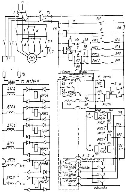
Rice. 1. Schematic diagram of a single elevator control
Let us consider the purpose of the remaining elements of the circuit and its operation using the example of moving a cabin with a passenger from the 1st to the 3rd floor, assuming that the automatic machine A, the disconnector P and the limit switches KB limiting the movement of the cabin up and down in emergency modes, are closed and the cabin is on the ground floor. In this case, the coils of the RIS relay, in addition to the relay of the first floor, flow from the rated current.
When the button «3rd floor» is pressed, the following electrical circuit is formed: network phase — pole of the disconnector P — fuse Pr — limit switch KB — button «Stop» — locking of the mine doors D1 — D4 — contacts for tensioning the rope KK — safety limit switch KL — cabin door switches DK — contacts of the «Stop» button — opening block -contact Н — relay coil RUV — closing contacts of relays RIS4 and RISZ (the coils of these relays carry current) — coil of floor relay ERZ — button «3rd floor» — opening blocks — contacts of contactors U, B, N — limit switch KB — fuse R — disconnector pole P — network phase.
After relay RUV and ER3 actuate, forward travel contactor B, fast travel contactor B (on coil circuit B — block contact ML — high-speed switch VB — relay contacts RISZ and ER3) are turned on. When contacts B and B are closed, the motor is connected to the mains, the contactor T, the release pulley and the shunt contactor KO, which turns on the shunt solenoid MO and prepares the circuit of the low-speed contactor coil Ml, are switched on. The stroke retracts, releasing the locking lever and the cab begins to move.
When the cabin approaches the third floor, the ferromagnetic shunt closes the coil of the TTSZ sensor, its resistance increases, and the RISZ relay disappears, turning off the ER3 and RUV relays. As a result, contactor B disappears, closing its contact, turns on the low-speed contactor Ml, and contactor B remains on, because when the car is moving, the magnetic circuit of the precise brake sensor is not yet closed, therefore, the RITOV contact still not yet open.The motor is stopped at low speed operating in generator mode with a resistor R. introduced in one phase of the stator.
As soon as the floor of the car is aligned with the floor of the floor, the magnetic shunt closes the magnetic circuit of the coil of the exact stop sensor DTOV, the relay RITOV disappears and the contactors B, then KO and finally ML are turned off. As a result, the motor electromagnet and the brake is disconnected from the mains, the mechanical brake is applied and the cab is stopped.
To learn a collective scheme for controlling elevators with passing stops only when lowering the car or a fully collective scheme, i.e. when passing stops while the car is moving up and down, it is necessary in a scheme similar to that discussed in fig. 1, introduce some additions. For example, in a two-speed motor circuit, the ID inductive sensors, the RIS relay, and the call and order buttons on each floor are included as shown in Fig. 2.
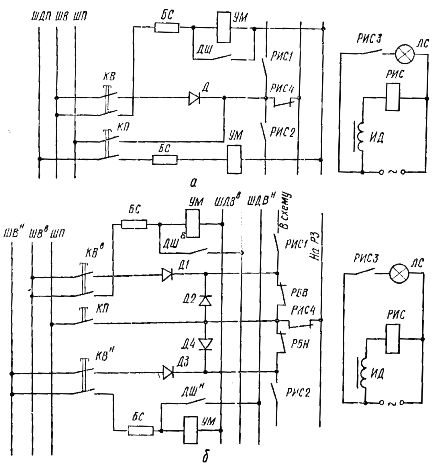
Rice. 2. Fragments of additions to collective elevator control schemes (one floor)
In a scheme with passing stops when lowering the cabin (Fig. 2, a), calls and orders are given by separate sticky buttons and therefore can be registered at any time and transmitted to the scheme immediately, except for the period of movement of the cabin with passengers up when the supply bus of the transfer contacts calls to the executive circuit are switched off by selective contacts from the positive bus.
In the complete selective control scheme (Fig. 2, b) there are additionally ringing circuits for boarding (ШДВв) and lowering (ШДВн) cabins, the contacts of blocking relays RBV and RBN are connected to the contacts of the selective sectional circuit executive circuit.
In the diagrams shown in Figs. 1 and 2, in the absence of a cabin on the floor, the coils of the ID inductive sensor and the RIS relay are energized. Therefore, when you press the command command button or call KV (they are held in the on state by the UM retaining magnets until they are overcome by the contacts of the mine doors on this floor of the DSh), a circuit is formed (not shown in figures) which includes the up control relay RUV if the destination floor is higher than the floor of the car park, or the down control relay LVL if the destination floor is below the car park.
After the arrival of the car at the call floor, the ID of the inductive sensor is vented, the RIS relay is turned off, opening its contacts, which turns off the RUV or RUN relay and the LS lamp (the car stops), and by closing the RIS4 contact, a circuit is prepared for the execution of the order coming from the car.
In the complete collective circuit, the circuit divided by the contacts RIS1 and RIS2 on the floor of the parking lot of the car is broken not only by these contacts, but also by the contacts of the blocking relay up RBV or down RBN (their coils are not shown in the diagram), and the raising, lowering, and ordering circuits are separated from each other by separating diodes D1 — D4.
Before pressing the call or order button, if the vehicle's direction of travel has not yet been selected, all contacts in the direction selection circuit are closed, except for the RIS4 contacts on the parking floor.Therefore, when one of these buttons is pressed, the call signals from the floors located above the floor of the car park are connected to the relay coil RUN, and the call signals from the floors below the car park include the relay RUV. After the direction is selected, simultaneously with the RUV or LVL relay, one of the opposite direction blocking relays RBV or RBN turns on, which interrupts the output through the sectional circuit of non-transient call signals with its contacts.
In the scheme shown in fig. 2, a, to lower the passengers, the cabin goes without stopping to the highest floor of the conversation and then descends with passing stops, and in the diagram shown in fig. 2, b, if it is necessary to pick up passengers, the cabin goes to the lowest floor of the call, then rises with passing stops.
In the considered schemes, the selectors are made on relay elements. Along with this, other selectors are used: cam, photoelectric, continuous brush tracking, stepping, on static elements, etc.
With large passenger flows, several elevators are installed in one corridor, which have combined control in pairs or groups to increase comfort and improve power. The number of elevators connected in groups usually does not exceed four, but more often three, although systems are known that contain up to eight elevators in a group.
In group control, there are usually three main modes of elevator operation: peak ascent, peak descent, and balanced movement in both directions. Activation of the elevators for one or another mode is carried out by the dispatcher or automatically by means of the programming clock installed for each group of elevators.
In high-rise buildings, each group of elevators is fixed to serve a certain area of floors, other floors are not served by it. If there are several elevators in the group serving one area or a low-rise building, in order to increase the average speed of movement by reducing the number of stops, separate elevators can be allocated to serve the even and odd floors.
To effect dual or group control of elevators, their control circuits must be collective and calls to each floor in both directions must be registered separately in each direction by suitable storage devices containing relays, transistors, etc.
As an example reflecting the specifics of operation in paired control of elevators with additional parking relays of the first elevator 1PC and the second elevator 2PC, consider a fragment of the schematic diagram shown in fig. 3.
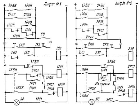
Rice. 3. Fragment of a schematic diagram of paired elevator control: ER — floor relay, RPK — channel switching relay, RVP automatic start relay
In this case, the car that descended with passengers on the first floor does not answer calls from other floors and waits for passengers. If there is no car on the first floor, then the car that rose by order and is released is automatically sent to the first floor, and when another car is lowered or parked, the last one remains on the floor at the end of the flight or goes to the loading center and is used for call operation mainly in the sinking direction.
The first floor cabin parking relay 1PC1 or 2PC1 is turned on after the arrival of the first floor cabin from the limit switch 1KVN or 2KVN (installed in the copier mines). These relays are blocked.Therefore, the inclusion of one of them indicates that this car arrived at the first floor earlier than the other. In this case, relay 1PC1 or 2PC1 with its closing contact turns on the LS signal lamp and with its opening contact breaks the ringing circuit of its elevator, interrupting the call while the car is parked on the first floor.
When the car leaves the first floor, its LS signal lamp goes out, the power to the called circuits of this elevator is restored immediately after the car is released, and after the car of another elevator arrives at the first floor, its computer relay is turned on. This cabin remains on the ground floor and waits for passengers (which is signaled by lighting the LS warning light). When the car that has risen to order is released and there are no calls, a signal is sent to the circuit that turns on the relay coils 1RUN or 2RUV 1RUN or 2RUV through the opening contacts of the limit switch 1KVN or 2KVN, and the car goes to the first floor, and t .n.
The motor control equipment of typical single, double and group control elevators is usually located on typical panels, stations or control units installed in machine rooms.