Electric trolley drive with overhead cranes
A trolley with an overhead crane is an independent element of a lifting device and is designed to move loads within the range of the overhead crane with a technologically determined speed of movement and the necessary accuracy of positioning the load. The bogie drive is one of the main components of overhead crane equipment.
The trolley moves on the track of an overhead crane. The bridge itself moves in a direction perpendicular to the direction of motion of the cart. A lifting mechanism is installed on the cart, which is equipped with a hook (or electromagnet) with which you can move the load. The movement of the bogie is an integral part of the technological cycle of the overhead crane (Fig. 1).
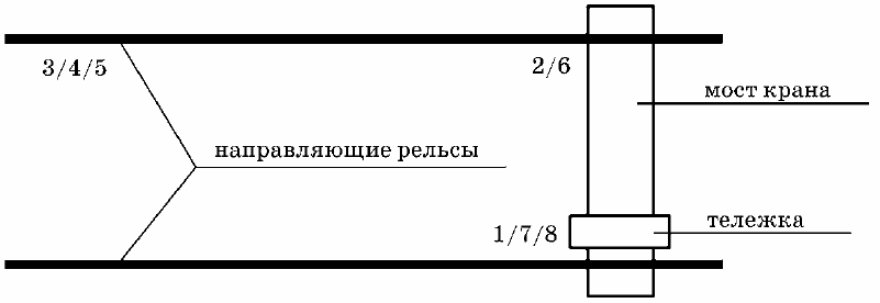
Rice. 1. Scheme for carrying out operations with a bridge crane in a working cycle
This cycle consists of the following operations (in Figure 1, operation numbers are shown in numbers):
1 — lifting the load;
2 — moving the cart to a given position;
3 — moving the crane to a predetermined position;
4 — reducing the weight of the burden;
5 — lifting the hook with the weight of the load;
6 — moving the crane to its original position;
7 — moving the cart to its original position;
8 — lowering the hook.
As can be seen from the process cycle of the overhead crane, the trolley drive motor is turned on in the second and seventh operations. When the bogie approaches a given position in the distance of the overhead crane, the electric motor of the bogie drive is electrically braked to ensure the required braking accuracy.
The engine is then switched off and a mechanical brake is applied. In addition, the electric drive of the bridge movement is turned on and the load moves along the workshop according to the technological task. Reaching the designated place, the crane stops, the load is lowered, and then the necessary technological operations are carried out.
The kinematic diagram of the trolley movement mechanism with overhead cranes is shown in Figure 2. The trolley movement mechanism is made according to the scheme with a gearbox in the middle between the drive wheels.
The drive from the electric motor D through the brake disc T, gearbox P, clutches M and shafts B is transmitted to the running wheels. A brake pulley is used to keep the cart stationary.
The cart has four travel wheels and two drive wheels. The traveling wheels of crane trolleys are usually made with two ribs.
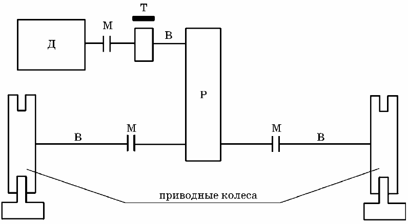
Rice. 2. Kinematic diagram of the trolley movement mechanism
The time to move the cart to the specified position will be determined by taking into account the time to accelerate and decelerate the cart with the required acceleration.Based on the conditions of the technological process, the tachogram when moving the cart should have the form shown in Figure 3.
It is necessary to ensure a smooth start of the bogie mechanism to a given speed with the required acceleration. To ensure the necessary positioning accuracy, a smooth deceleration of the electric drive with a transition to reduced speed is required, after which the trolley stops.
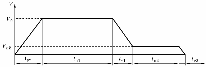
Rice. 3. Tachogram of the trolley movement mechanism
The movement of the bogie with impacts on the metal structure in the rail joints, intense acceleration and deceleration, natural vibrations of the metal structure when the machines are loaded cause very intense mechanical impacts on the electrical equipment located on the bridge crane bogie. Based on this, the electric drive for moving the trolley must meet the following requirements:
1) the electric drive must provide the ability to start the mechanism in motion, reverse the direction of movement and stop the mechanism with the required acceleration (m / s2) and correct positioning accuracy (mm);
2) the electric drive must provide smooth speed control down from the main;
3) the developed engine torque must ensure the operation of the mechanism at a given intensity;
4) at a given number of engine starts per hour, there should be no overheating of its windings, due to which a prolonged stoppage of the mechanism is possible;
5) the motor must be selected in accordance with the operating conditions, that is, it must have a suitable design, and its windings must be heat-resistant and have insulation against moisture;
6) the drive motor must have the smallest flywheel masses that have a significant impact on the flow of transients during frequent drive starts;
7) the drive motor must match the power of the running mechanism and have the necessary overload capacity;
8) the electric drive must ensure the formation of transient processes with minimum duration;
9) safety and ease of maintenance must be taken into account in the design of the electric drive.
The static moment for motion mechanisms operating on a horizontal track line in a production facility is created by sliding frictional forces in the bearings and rolling friction of the bogie wheels rolling on the rails of the overhead crane. The static moment of the mechanism during the forward movement of the trolley is determined by the lifting capacity of the crane. The static moment of the mechanism during the reverse movement of the bogie is calculated for an incomplete load.
For electric drive of the trolley of overhead cranes, asynchronous squirrel-cage rotor motors (incl as part of a variable frequency drive), wound rotor induction motors and independently excited DC motors.