Sources of harmonics in electrical networks
Since non-linear elements are invariably present in modern electrical, especially in industrial networks, as a result, current curves and voltage curves are distorted, higher harmonics appear in networks.
First of all, non-sinusoidality is due to the presence of static converters, then - synchronous generators, welding machines, fluorescent lamps, arc furnaces, transformers, motors and other non-linear loads.
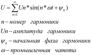
Mathematically, the non-sinusoidality of the current and voltage curves can be represented as the sum of the main harmonic of the mains frequency and its higher harmonics which are multiples of it. Harmonic analysis results in a trigonometric Fourier series, and the values of frequencies and phases of the resulting harmonics can be easily calculated using the formula:
In fact, the resulting combination of non-sinusoidal voltages and currents in a three-phase network can be asymmetrical or symmetrical.A symmetrical system of non-sinusoidal voltages for multiples of three harmonics (k = 3n) leads to the formation of a system of zero-sequence voltages.
Furthermore, at k = 3n + 1, the harmonic in the three-phase network generates a symmetrical system of negative sequence voltages. So every k-harmonic of a symmetrical system of non-sinusoidal voltages results in a symmetrical system of phase voltages of direct, reverse or zero sequence.
In practice, however, the system of phase non-sinusoidal voltages turns out to be asymmetric. So, magnetic cores of three-phase transformers themselves, they are nonlinear and asymmetric, since the lengths of the magnetic paths for the middle and final phases differ by a factor of 1.9. As a result, the effective values of the magnetizing currents of the middle phase are 1.3 — 1.55 times smaller than the values of the magnetizing currents for the final phases.
Asymmetric harmonics are decomposed into symmetric components when each k -harmonic forms an asymmetric system of phase voltages and typically contains components of three sequences—zero, forward, and reverse.
Three-phase networks with an isolated neutral are characterized by the absence of zero-sequence components in each of the phases, provided that there are no earth faults. As a result, there are no multiples of three harmonics in the phase currents, but there are other harmonics that contain reverse and positive sequence components.
Power rectifiers, as a rule, on the DC side have large inductances, which are DC machine windings and smoothing reactors.These inductances are many times higher than the equivalent inductance of the alternating current side, therefore such rectifiers with respect to the alternating current network behave as sources of higher harmonic current. The current directed to the network with a harmonic frequency has a value that does not depend on the parameters of the supply network.
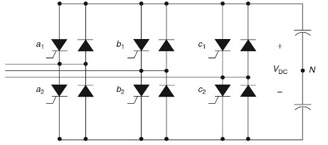
For three-phase electrical networks, it is characteristic to use three-phase full-wave rectifiers for 6 valves as such converters, from which they are called six-pulse or six-phase. The current curve for each of the phases in this case can be described by the equation (for the current of one phase A):
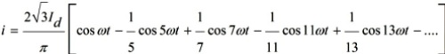
It can be seen that the phase currents contain only odd harmonics that are not multiples of three, and the signs of these harmonics alternate: positive harmonics of the 6k + 1st order and negative harmonics of the 6k-1st order.
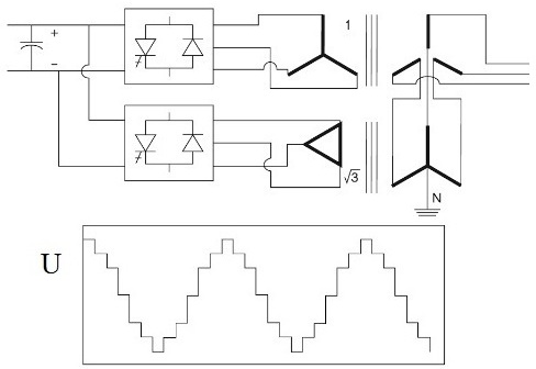
If a twelve-phase rectifier is used, when a pair of six-phase rectifiers is connected to a pair of three-phase transformers (the secondary voltages are phase-shifted by pi / 6), then harmonics of 12k + 1 and 12k- 1-orders will appear, respectively.
Before rectifiers were used, only transformers and various electrical machines were the main source of higher harmonics in electrical networks. But even today transformers are the most common elements of electrical networks.
The reason transformers generate higher harmonics is the non-linear magnetization curve of the magnetic circuits and the constant presence of hysteresis loops… A non-linear magnetizing curve and hysteresis loop generate distortions of the original sinusoidal no-load magnetizing current and the result is higher harmonics in the current that the transformer draws from the grid.
Transformers of the 110 kV class have no more than 1% no-load current, and transformers of the 6-10 kV class - no more than 2-3%. These are small currents and their active losses in the magnetic circuit are negligible. It is the magnetization curve that matters, not the hysteresis loop.
The magnetization curve is symmetrical and there are not even harmonics in the Fourier series expansion. The distortion of the magnetizing current is caused by odd harmonics, among which are multiples of three. The third harmonic is particularly pronounced, but the fifth and seventh harmonics are also the most significant.
EMF harmonics and current harmonics are also characteristic of motors, both synchronous and asynchronous… These harmonics are caused by the same phenomena as current harmonics generated by transformers—the non-linearity of the magnetization curve of the materials from which the stator and rotor are made.
The frequency spectrum of current harmonics of electric motors, like that of transformers, includes odd harmonics, among which are obviously multiples of three. The most significant here are the 3rd, 5th and 7th harmonics.
As in the case of transformers, rough calculations allow us to take the percentage of currents of the 3rd, 5th and 7th harmonics at 40% for the third harmonic, 30% for the fifth harmonic and 20% for the seventh harmonic (percentage of of the idle current).