Application of Ohm's law in practice
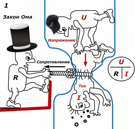
 I would like to begin to explain the working principle of one of the basic laws of electrical engineering with an allegory — showing a small caricature of 1 of three people named "Voltage U," "Resistance R," and "Current I."
It shows that «Tok» is trying to crawl through the contraction in the pipe, which «Resistance» is diligently tightening. At the same time «Voltage» makes the maximum possible effort to pass, press «Current».
This drawing is a reminder of that electricity Is the orderly movement of charged particles in a particular medium. Their movement is possible under the influence of applied external energy, which creates a potential difference — voltage. The internal forces of the wires and elements of the circuit reduce the magnitude of the current, resist its movement.
Consider a simple diagram 2 that explains the operation of Ohm's law for a section of a direct current circuit.
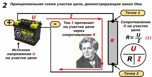
As a voltage source U we use battery, which we connect to the resistance R with thick and at the same time short wires at points A and B.Assume that the wires do not affect the value of the current I through the resistor R.
Formula (1) expresses the relationship between resistance (ohms), voltage (volts) and current (amps). They call her Ohm's law for a section of a circuit… The formula circle makes it easy to remember and use to express any of the constituent parameters U, R, or I (U is above the dash, and R and I are below).
If you need to determine one of them, then close it mentally and work with the other two, performing arithmetic operations. When the values are on one row, we multiply them. And if they are located at different levels, we perform the division of the upper to the lower.
These relationships are shown in formulas 2 and 3 in Figure 3 below.
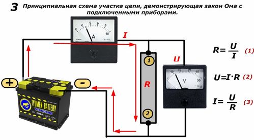
In this circuit, an ammeter is used to measure the current, which is connected in series with the load R, and the voltage is a voltmeter connected in parallel to points 1 and 2 of the resistor. Taking into account the design features of the devices, let's say that the ammeter does not affect the current in the circuit, and the voltmeter does not affect the voltage.
Determination of resistance by Ohm's law
Using the readings of the devices (U = 12 V, I = 2.5 A), you can use formula 1 to determine the resistance value R = 12 / 2.5 = 4.8 Ohm.
In practice, this principle is included in the operation of measuring devices - ohmmeters, which determine the active resistance of various electrical devices.Since they can be configured to measure different ranges of values, they are respectively subdivided into microohms and milliohms, operating with low resistance, and tera-, hygo-, and megohms- measuring very large values.
For specific working conditions, they are produced:
-
portable;
-
shield;
-
laboratory models.
The principle of operation of an ohmmeter
Magnetoelectric devices are commonly used to make measurements, although electronic (analog and digital) devices have recently been widely introduced.
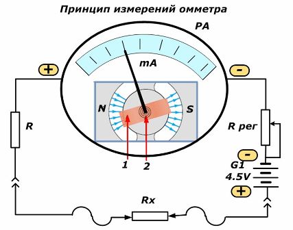
The magnetoelectric system ohmmeter uses a current limiter R that only passes milliamps and a sensitive measuring head (milliammeter) through it. It reacts to the flow of small currents through the device due to the interaction of two electromagnetic fields from the permanent magnet N-S and the field created by the current passing through the winding of the coil 1 with a conductive spring 2.
As a result of the interaction of the forces of the magnetic fields, the arrow of the device deviates from a certain angle. The scale on the head is immediately graduated in ohms for easier operation. In this case, the expression of current resistance according to formula 3 is used.
The ohmmeter must maintain a stable supply voltage from the battery to ensure accurate measurements. For this purpose, calibration is applied using an additional regulating resistor R reg. With its help, before the start of the measurement, the supply of excess voltage from the source is limited to the circuit, a strictly stable, normalized value is set.
Determination of voltage by Ohm's law
When working with electric circuits, there are times when it is necessary to determine the voltage drop on an element, for example, a resistor, but its resistance, which is usually marked on the box, and the current passing through it are known. To do this, you do not need to connect a voltmeter, but it is enough to use the calculations according to formula 2.
In our case, for Figure 3, we make calculations: U = 2.5 4.8 = 12 V.
Determination of current according to Ohm's law
This case is described by formula 3. It is used to calculate loads in electrical circuits, select the cross-sections of wires, cables, fuses or circuit breakers.
In our example, the calculation looks like this: I = 12 / 4.8 = 2.5 A.
Bypass surgery
This method in electrical engineering is used to disable the operation of certain elements of the circuit without disassembling them. To do this, short-circuit the input and output terminals (in Figure 1 and 2) with a wire to an unnecessary resistor - remove them.
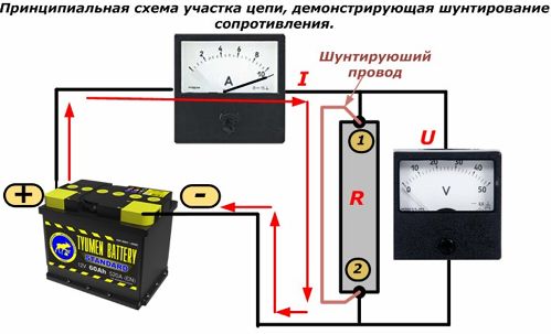
As a result, the circuit current chooses a path of less resistance through the shunt and rises sharply, and the voltage of the shunt element drops to zero.
Short circuit
This mode is a special case of bypass and is usually shown in the above figure when the short circuit is installed at the output terminals of the source. When this happens, very dangerous high currents are created that can shock people and burn unprotected electrical equipment.
Protection is used to combat accidental faults in the electrical network. They are set to such settings that do not interfere with the operation of the circuit in normal mode.They cut the power only in case of emergency.
For example, if a child accidentally plugs a wire into a household outlet, then a properly configured automatic switch on the apartment entrance board will almost immediately turn off the power.
Everything described above refers to Ohm's law for a section of a DC circuit, not a complete circuit where there may be many more processes. We must imagine that this is only a small part of its application in electrical engineering.
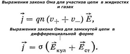
The patterns identified by the famous scientist Georg Simon Ohm between current, voltage and resistance are described in different ways in different AC environments and circuits: single-phase and three-phase.
Here are the basic formulas that express the ratio of electrical parameters in metal conductors.
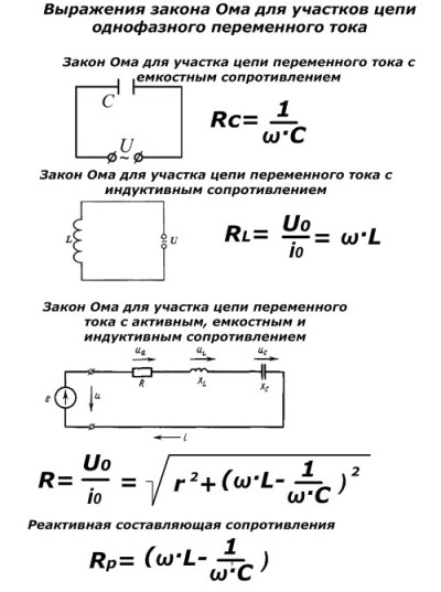
More complex formulas to perform special Ohm's law calculations in practice.
As you can see, the research conducted by the brilliant scientist Georg Simon Ohm is of great importance even in our time of rapid development of electrical engineering and automation.