Active resistance and inductor in AC circuit
Considering an AC circuit containing only inductive resistance (see the article «Inductor in an alternating current circuit»), we assumed that the active resistance of this circuit is zero.
In fact, both the wire of the coil itself and the connecting wires have a small but active resistance, so the circuit inevitably consumes the energy of the current source.
Therefore, when determining the total resistance of an external circuit, it is necessary to add its reactive and active resistances. But it is impossible to add these two resistances which are different in nature.
In this case, the impedance of the circuit to the alternating current is found by geometric addition.
A right-angled triangle (see figure 1) is constructed, one side of which is the value of the inductive resistance, and the other side is the value of the active resistance. The desired circuit impedance is determined by the third side of the triangle.
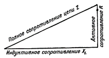
Figure 1. Determination of the impedance of a circuit containing inductive and active resistance
Circuit impedance is denoted by the Latin letter Z and is measured in ohms. It can be seen from the construction that the total resistance is always greater than the inductive and active resistance taken separately.
The algebraic expression for the total circuit resistance is:

where Z — total resistance, R — active resistance, XL — inductive resistance of the circuit.
Therefore, the total resistance of a circuit to alternating current, consisting of active and inductive resistance, is equal to the square root of the sum of the squares of the active and inductive resistance of this circuit.
Ohm's Law since such a circuit is expressed by the formula I = U / Z, where Z is the total resistance of the circuit.
Let us now analyze what the voltage will be if the circuit, in addition to and and the phase shift between the current and the inductance, also has a relatively large active resistance. In practice, such a circuit can be, for example, a circuit containing an iron-core inductor wound by a thin wire (high-frequency choke).
In this case, the phase shift between current and voltage will no longer be a quarter of a period (as it was in a circuit with only inductive resistance), but much less; and the greater the resistance, the less phase shift will result.
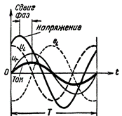
Figure 2. Current and voltage in a circuit containing R and L.
Now she herself EMF of self-induction is not in anti-phase with the current source voltage, as it is offset with respect to the voltage not by half a period, but by less.In addition, the voltage created by the current source at the terminals of the coil is not equal to the emf of self-induction, but is greater than it by the amount of the voltage drop in the active resistance of the coil wire. In other words, the voltage in the coil consists anyway of two components:
-
tiL- the reactive component of the voltage, which balances the effect of EMF from self-induction,
-
tiR- the active component of the voltage that will overcome the active resistance of the circuit.
If we connect a large active resistance in series with the coil, the phase shift will decrease so much that the current sine wave will almost catch up with the voltage sine wave and the difference in phases between them will be barely noticeable. In this case, the amplitude of the term and will be greater than the amplitude of the term.
Similarly, you can reduce the phase shift and even completely reduce it to zero if you reduce the frequency of the generator in some way. A decrease in frequency will result in a decrease in self-induction EMF and therefore a decrease in the phase shift between the current and the voltage in the circuit caused by it.
The power of an AC circuit containing an inductor
The alternating current circuit containing the coil does not consume the energy of the current source and that in the circuit there is an energy exchange process between the generator and the circuit.
Let us now analyze how things will be with the power consumed by such a scheme.
The power consumed in an AC circuit is equal to the product of current and voltage, but since current and voltage are variable quantities, then the power will also be variable.In this case, we can determine the power value for each moment in time if we multiply the current value by the voltage value corresponding to a given moment in time.
To get the power graph, we need to multiply the values of the straight line segments that define the current and voltage at different times. Such a construction is shown in fig. 3, a. The dashed waveform p shows us how power changes in an AC circuit containing only inductive resistance.
The following algebraic multiplication rule was used in constructing this curve: When a positive value is multiplied by a negative value, a negative value is obtained, and when two negative or two positive values are multiplied, a positive value is obtained.
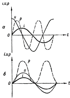
Figure 3. Power graphs: a — in a circuit containing inductive resistance, b — also, active resistance
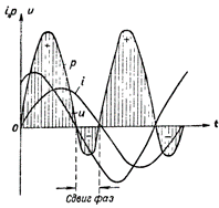
Figure 4. Power plot for a circuit containing R and L.
The power curve in this case lies above the time axis. This means that there is no exchange of energy between the generator and the circuit and therefore the power supplied by the generator to the circuit is completely consumed by the circuit.
In fig. 4 shows the power plot for a circuit containing both inductive and active resistance. In this case, the reverse transfer of energy from the circuit to the current source also occurs, but to a much lesser extent than in a circuit with a single inductive resistance.
After reviewing the above power graphs, we conclude that only the phase shift between current and voltage in the circuit creates "negative" power.In this case, the greater the phase shift between the current and voltage in the circuit, the less power will be consumed by the circuit, and conversely, the smaller the phase shift, the greater the power consumed by the circuit.
Read also: What is voltage resonance
