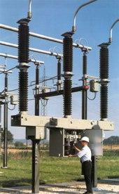
The main types and electrical characteristics of the internal insulation of electrical installations
General properties of the internal insulation of electrical installations
Internal insulation refers to parts of the insulating structure in which the insulating medium is liquid, solid or gaseous dielectrics or their combinations, which do not have direct contact with atmospheric air.
The desirability or necessity of using indoor insulation rather than ambient air is due to a number of reasons.
First, the internal insulation materials have a significantly higher electrical strength (5-10 times or more), which can sharply reduce the insulation distances between the wires and reduce the size of the equipment. This is important from an economic point of view.
Secondly, the individual elements of the internal insulation perform the function of mechanical fastening of wires; liquid dielectrics in some cases significantly improve cooling conditions for the entire structure.
 Internal insulating elements in high-voltage structures during operation are exposed to strong electrical, thermal and mechanical loads. Under the influence of these influences, the dielectric properties of the insulation deteriorate, the insulation "ages" and loses its electrical strength.
Thermal effects are caused by heat release in the active parts of the equipment (in wires and magnetic circuits) as well as dielectric losses in the insulation itself. In conditions of increased temperature, the chemical processes in the insulation accelerate significantly, which leads to a gradual deterioration of its properties.
Mechanical loads are dangerous for the internal insulation, because microcracks can appear in the solid dielectrics that make it up, where then, under the influence of a strong electric field, partial discharges will occur and the aging of the insulation will accelerate.
A special form of external influence on the internal insulation is caused by the contacts with the environment and the possibility of contamination and moisture of the insulation in case of leakage of the installation. Wetting the insulation leads to a sharp decrease in leakage resistance and an increase in dielectric losses.
Properties of insulation as a dielectric
Insulation is mainly characterized by DC resistance, dielectric loss and electrical strength. The electrically equivalent isolation circuit can be represented by connecting capacitors and resistors in parallel. In this regard, when a constant voltage is applied to the insulation, the current in it decreases exponentially and the measured resistance value increases accordingly.The established value of the insulation resistance R from it characterizes the external pollution of the insulation and the presence of passing current paths in it. In addition, hydration insulation can also be characterized by the absolute value of the capacity and the dynamics of its change.
Destruction of the internal insulation of electrical equipment
In the event of a high voltage fault, the internal insulation completely or partially loses its dielectric strength. Most types of internal insulation belong to the group of non-recoverable insulations, the breakdown of which means irreversible damage to the structure. This means that the internal insulation must have a higher dielectric strength than the external insulation, i.e. such a level that failures are completely excluded during the entire service life.
The irreversibility of internal insulation damage greatly complicates the accumulation of experimental data for new types of internal insulation and for newly developed large insulation structures of high and ultra-high voltage equipment. After all, each piece of large, expensive insulation can only be tested for failure once.
Dielectrics used to produce internal insulation of electrical equipment
Dielectricsequipment used for the production of high-voltage internal insulation must possess a complex of high electrical, thermophysical and mechanical properties and provide: the required level of dielectric strength, as well as the required thermal and mechanical characteristics of the insulating structure with dimensions that meet the high technical and economic indicators of the entire installation as a whole.
Dielectric materials must also:
-
have good technological properties, i.e. must be suitable for high-throughput internal isolation processes;
-
meet environmental requirements, i.e. they must not contain or form toxic products during operation, and after the entire resource has been used up, they must undergo processing or destruction without polluting the environment;
-
not to be scarce and to have such a price that the isolation structure is economically viable.
In some cases, other requirements may be added to the above requirements due to the specifics of a particular type of equipment. For example, materials for power capacitors must have an increased dielectric constant; materials for distribution chambers — high resistance to thermal shocks and electric arcs.
The long-term practice of creating and operating various high-voltage equipment shows that in many cases the entire set of requirements is best satisfied when a combination of several materials is used as part of the internal insulation, complementing each other and performing slightly different functions.
Thus, only solid dielectric materials provide the mechanical strength of the insulating structure; they usually have the highest dielectric strength. Parts made of a solid dielectric with high mechanical strength can act as a mechanical anchor for wires.
High-strength gases and liquid dielectrics easily fill insulation gaps of any configuration, including the smallest gaps, pores and cracks, thereby significantly increasing dielectric strength, especially in the long term.
The use of liquid dielectrics makes it possible in some cases to significantly improve the cooling conditions due to the natural or forced circulation of the insulating liquid.
Types of internal insulation and materials used for their production.
Several types of internal insulation are used in high voltage installations and power system equipment. The most common are paper-impregnated (paper-oil) insulation, oil barrier insulation, mica-based insulation, plastic and gas.
These varieties have certain advantages and disadvantages and have their own areas of application. However, they share some common properties:
-
the complex nature of the dependence of the dielectric strength on the duration of exposure to voltage;
-
in most cases, irreversible destruction by demolition;
-
influence on the behavior during operation of mechanical, thermal and other external influences;
-
in most cases a predisposition to aging.
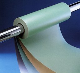
Impregnated Paper Insulation (BPI)
The starting materials are special electrical insulating papers and mineral (petroleum) oils or synthetic liquid dielectrics.
Paper-impregnated insulation is based on paper layers. Roll-impregnated paper insulation (roll width up to 3.5 m) is used in sections of power capacitors and in bushings (sleeves); tape (tape width from 20 to 400 mm) — in structures with electrodes of relatively complex configuration or long length (sleeves of higher voltage classes, power cables). Layers of tape insulation can be wound on the electrode with an overlap or with a gap between adjacent turns.After winding the paper, the insulation is dried under vacuum at a temperature of 100-120 ° C to a residual pressure of 0.1-100 Pa. The paper is then impregnated with well degassed oil under vacuum.
A paper defect in paper-impregnated insulation is confined to one layer and is repeatedly overlapped by other layers. The thinnest gaps between the layers and a large number of micropores in the paper itself during vacuum drying remove air and moisture from the insulation, and during impregnation, these gaps and pores are reliably filled with oil or another impregnating liquid.
Capacitor and cable papers have a homogeneous structure and high chemical purity. Condenser papers are the thinnest and purest. Transformer papers are used in bushings, current and voltage transformers, as well as in longitudinal insulation elements of power transformers, autotransformers and reactors.
For impregnation of paper insulation in power oil-filled cables 110-500 kV, with low viscosity oil or synthetic cable oils, and in cables up to 35 kV — oil-filled mixtures with increased viscosity.
Impregnation is carried out in power and measuring transformers and bushings transformer oil… Use of power capacitors capacitor oil (petroleum), chlorinated biphenyls or their substitutes and castor oil (in impulse capacitors).
Petroleum cable and capacitor oils are more thoroughly refined than transformer oils.
Chlorinated biphenyls possessing a high relative dielectric constant, increased resistance to partial discharges (PD) and non-combustibility, they are toxic and hazardous to the environment. Therefore, the scale of their use is sharply reduced, they are replaced by environmentally friendly liquids.
To reduce the dielectric losses in the power capacitors, a combined insulation is used, in which the layers of paper are alternated with layers of polypropylene film, which is an order of magnitude smaller than untreated paper. Such insulation has a higher electrical strength.
The disadvantages of insulation impregnated with paper are the low permissible operating temperature (not more than 90 ° C) and flammability.

Oil barrier (oil filled) insulation (MBI).
This insulation is based on transformer oil. It ensures good cooling of the structure due to spontaneous or forced circulation.
Solid dielectric materials are also part of the oil barrier insulation — electrical cardboard, cable paper, etc. They provide mechanical strength to the structure and are used to increase the dielectric strength of oil barrier insulation. The baffles are made of electrical cardboard and the electrodes are covered with layers of cable paper. Barriers increase the dielectric strength of insulation with an oil barrier by 30-50%, dividing the insulation gap into a number of narrow channels, they limit the amount of impurity particles that can approach the electrodes and participate in the initiation of the discharge process.
The electrical strength of the oil barrier insulation is increased by covering complex-shaped electrodes with a thin layer of polymeric material, and in the case of simple-shaped electrodes by insulating with layers of paper tape.
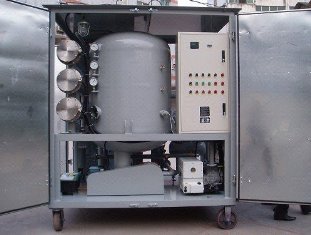
The technology for the production of insulation with an oil barrier includes assembly of the structure, drying under vacuum at a temperature of 100-120 ° C and filling (impregnation) under vacuum with degassed oil.
The advantages of oil-barrier insulation include the relative simplicity of the design and technology of its production, intensive cooling of the active parts of the equipment (windings, magnetic circuits), as well as the possibility of restoring the quality of the insulation during operation by drying the structure and changing the oil .
The disadvantages of insulation with an oil barrier are the lower electrical strength than paper-oil insulation, the danger of fire and explosion of the structure, the need for special protection against moisture during operation.
Oil insulation insulation is used as the main insulation in power transformers with a nominal voltage of 10 to 1150 kV, in autotransformers and reactors with higher voltage classes.
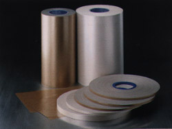
Mica-based insulation has heat resistance class B (up to 130 ° C). Mica has a very high dielectric strength (at a certain orientation of the electric field relative to the crystal structure), is resistant to partial discharges, and is highly resistant to heat. Thanks to these properties, mica is an indispensable material for insulating the stator windings of large rotating machines. The main starting materials are mica strip or glass mica strip.
Micalenta is a layer of mica plates connected with varnish to each other and with a substrate made of special paper or glass tape. Mikalenta is used in so-called complex insulation, the production process of which includes winding several layers of mica tape, impregnation with a bituminous compound under vacuum heating and pressing. These operations are repeated every five to six layers until the required insulation thickness is obtained. Complex insulation is currently used in small and medium-sized machines.
Insulation from glass mica strips and thermosetting impregnating compounds is more perfect.
Mica tape consists of one layer of 0.04 mm thick mica paper and one or two layers of 0.04 mm thick glass tape. Such a composition has sufficiently high mechanical strength (due to substrates) and the above-mentioned qualities characteristic of mica.
 Mica strips and impregnating compositions based on epoxy and polyester resins are used to make thermoset insulation, which does not soften when heated, retains high mechanical and electrical strength. The types of thermoset insulation used in our country are called "mica", "monolith", "monotherm", etc. Thermosetting insulation is used in the stator windings of large turbos and hydro-generators, motors and synchronous compensators with a nominal voltage of up to 36 kV.
Plastic insulation on an industrial scale is used in power cables for voltages up to 220 kV and in impulse cables. The main dielectric material in these cases is low and high density polyethylene. The latter has better mechanical properties but is less machinable due to its higher softening temperature.
The plastic insulation in the cable is sandwiched between semiconducting shields made of carbon-filled polyethylene. The screen on the current-carrying wire, the polyethylene insulation and the outer shield are applied by extrusion (extrusion). Some types of impulse cables use interlayers of fluoroplastic tape. In some cases, polyvinyl chloride is used for protective cable sheaths.
Gas insulation
It is used to perform gas insulation in high voltage structures SF6 gas or sulfur hexafluoride… It is a colorless, odorless gas about five times heavier than air.It has the greatest strength compared to inert gases such as nitrogen and carbon dioxide.
Pure SF6 gas is harmless, chemically inactive, has increased heat dissipation ability and is a very good arc suppression medium; does not burn or sustain combustion. The dielectric strength of SF6 gas under normal conditions is approximately 2.5 times that of air.
The high dielectric strength of SF6 gas is explained by the fact that its molecules easily bind electrons, forming stable negative ions. Therefore, the process of multiplication of electrons in a strong electric field, which is the basis for the development of an electric discharge, becomes difficult.
As pressure increases, the dielectric strength of SF6 gas increases almost proportionally to pressure and can be higher than that of liquid and some solid dielectrics. The highest operating pressure and therefore the highest level of dielectric strength of SF6 in an insulating structure is limited by the possibility of liquefaction of SF6 at low temperatures, for example, the liquefaction temperature of SF6 at a pressure of 0.3 MPa is -45 ° C. and at 0.5 MPa it is -30 ° C. Such temperatures for turned off outdoor equipment are quite possible in winter in many parts of the country.
Insulating support structures made of cast epoxy insulation are used to secure live parts in combination with SF6 gas.
SF6 gas is used in circuit breakers, cables and hermetically sealed switchgear (GRU) for voltages of 110 kV and above and is a very promising insulating material.
At temperatures above 3000 ° C, the decomposition of SF6 gas can begin with the release of free fluorine atoms.Gaseous toxic substances are formed. The probability of their occurrence exists for some types of switches designed to disconnect large short-circuit currents. Since the switches are hermetically sealed, the release of poisonous gases is not dangerous to the operating personnel and the environment, but special precautions must be taken when repairing and opening the switch.