Bolted contact connections
 The connection between rectangular wires is made with the help of bolts, studs or clamps. The number of bolts is determined by the size of the tires. It is more expedient to ensure the compressive force of the contact surfaces using several bolts with a smaller section than one bolt with a larger section, since in the first case the number of contact spots is greater. As a result, the junction resistance of the connection decreases and a more even distribution of the current over the contact area is obtained. Flat and pin contact wires of electrical devices are made in accordance with GOST 21242-75.
Connecting several parallel buses the phases between each other are carried out by laying them in connection, and not in pairs, since in the second case the contact surface is much smaller, and the transient resistance is large.
When an electric current passes, the parts of the contact connection heat up and expand due to heating. Particularly significant heating and expansion occurs during a short circuit. The expansion is not the same throughout the contact link because its parts have different coefficients of linear expansion.
Copper and aluminum busbar bolts work under unfavorable conditions, because the coefficient of linear expansion of a steel bolt is lower than that of a copper or aluminum busbar: in addition, in the event of a short circuit, the bolts always heat up significantly less than the tires.
In the short-circuit mode, additional forces act on the bolts, which, in combination with the tightening force of the bolt, can lead to permanent deformations and weakening of the contact connection when the temperature drops. The thicker the tire pack, the greater the mechanical stresses in the clamping bolts. These stresses can be reduced using Belville springs.
Disc springs for electrical purposes are produced in accordance with GOST 17279-71 of two types:
— Ш — springs to maintain the contact pressure in the tire joints,
— K — springs for maintaining the contact pressure in the connections of the cable lugs with the terminals of the electrical equipment, which have a reduced contact plane compared to tires
The main parameters of the springs are shown in fig.

Rice. 1. Belleville Spring.
It is allowed to make connections without using Belleville springs, but with a thickened washer installed on the aluminum side under the head of the bolt or under the nut. The dimensions of normal (GOST 11371-78) and extended (GOST 6958-78) washers are given in the reference tables.
The length of overlap (overlap) of the connected elements in the contact connection with one or four bolts rarely exceeds the width of the busbar, and with two bolts it is from 1.5 to 2 times the width of the busbar.
A reduction in the contact resistance of the contact joint is achieved by increasing the pressure and reducing the stiffness.
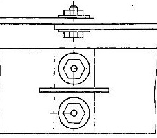
Fig. 2. Contact connection of tires with a longitudinal section.
To reduce the stiffness of the contact connection of the tires, make longitudinal cuts with a width of 3-4 mm, a length of 50 mm (Fig. 2).
The bolts in the joint are selected based on the required specific pressures between the contact surfaces of the apparent current density and the allowable tensile forces for the bolts. The recommended specific pressures in contact joints, MPa, depending on the material of the contact joint, are given below.
Tinned copper — 0.5 — 10.0
Copper, brass, bronze, unpreserved — 0.6 — 12.0
Aluminum — 25.0
Tinned steel — 10.0 — 15.0
Bare steel — 60.0
The length of the bolts is chosen so that at least two threads of free thread remain after assembly and tightening of the connections.
The bolts of the contact connections are tightened with a wrench, ensuring the torque values given in the reference tables.
Belleville spring bolts are tightened in two steps. First, the bolt is tightened until the Belleville spring is fully compressed, then the connection is loosened by turning the wrench in the opposite direction 1/4 turn for MB and M12 bolts and 1/6 turn for other bolts.
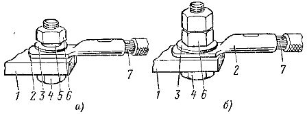
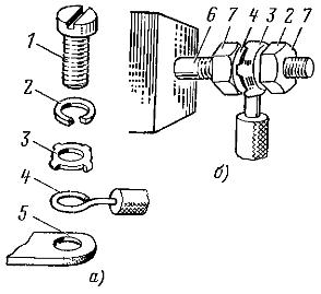
Rice. 3. Connecting a copper wire with a copper or aluminum alloy flat terminal: a — for bolts up to M8, b — for all sizes of bolts, 1 — terminal, 2 — tip, 3 — washer, 4 — bolt, 5 — spring washer , 6 — nut, 7 — core.
The connection of flat wires to flat copper or aluminum alloy terminals (Fig.3) is carried out with the help of steel bolts (GOST 7798-70), nuts (GOST 5915-70) and washers (GOST 11371-78) and the terminals made of aluminum - using means to stabilize the contact pressure: springs from Belville or fasteners made of copper or aluminum alloys with a coefficient of linear expansion (18-21) x 10-6 ° C-1 (Fig. 4).
When assembling the Belleville spring link, an enlarged washer is placed on the side of the aluminum outlet, and a normal washer is placed on the side of the copper lug on the tip. Containers are not used in Belleville springs.
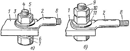
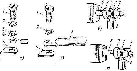
Rice. 4. Connecting a copper wire to a flat aluminum outlet: a — using Belleville springs, b — using non-ferrous fasteners, 1 — terminal, 2 — copper tip, 3 — spring washer, 4 — steel bolt, 5 — steel nut , 6 — enlarged steel washer, 7 — disc spring, 8 — copper wire, 9 — bolt of non-ferrous metals, 10 — nut of non-ferrous metals, 11 — washer of non-ferrous metals.
If disc springs or non-ferrous bolts and nuts of the required dimensions are not available, the connection can be made using an enlarged washer, provided that the junction resistance and the heating temperature of the connection are within the specified limits.
Rice. 5. Attach two lugs to the flat terminal.
In cases where the contact connections are operated in a room with a relative humidity above 80% and a temperature of at least 20 ° C or in a chemically active environment, it is carried out using transitional copper-aluminum plates. Direct connection of a copper wire to an aluminum terminal can be done when the aluminum terminal has a protective metal coating.
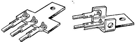
Rice. 6. Adapters for connecting more than two ears to the terminals.
When making the connection to the flat terminal of the two conductors of the cable, the lugs should be placed on both sides of the flat terminal (Fig. 5) to ensure the lowest contact resistance and to maintain a more even distribution of current . If you need to connect more than two ears to a terminal or the terminal hole does not match the terminal hole, use transition pieces. The tips are connected to the adapter part symmetrically (Fig. 6).
Connecting flat copper wires and lugs to pins equipment pins is carried out using standard nuts of copper and its alloys. Connections at rated currents up to 30 A are made using steel nuts coated with tin, nickel or cadmium.
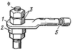
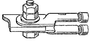
Rice. 7. Attaching the tip to the pin terminal: 1 — tip, 2 — enlarged copper nut, 3 — steel nuts, 4 — pin terminal, 5 — wire.
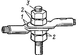
Rice. 8. Connecting two lugs with a pin terminal: 1 — lugs, 2 — nuts, 3 — pin terminal.
Aluminum flat conductors for currents up to 250 A are connected in the same way as copper, and for currents from 250 to 400 A, extended traction nuts are used for connection (Fig. 7).
The connection of two lugs to the pin terminal (Fig. 8) must be done symmetrically, and adapter parts are used when connecting more than two lugs.
For currents above 400 A, copper-aluminum lugs must be used or the ends of the busbars must be reinforced (lined).
The connection of round wires to flat and pin terminals is carried out after forming them in the form of a ring with the help of star-shaped washers.When tightening the screw or nut, the teeth of the star washers must not touch the outlet surface or the stop nut so that the core ring is firmly pressed against the clamp.
The wire ring is placed under the head of the bolt or nut so that it is not pushed out from under them when the bolts or nuts are tightened (Fig. 9). In cases where the single wire aluminum conductor is terminated with a ring tip (piston), the star washer is not used.
Rice. 9. Connection of an aluminum wire with a cross section of up to 10 mm2 with conductors: a — flat, b — pin, 1 — screw, 2 — spring washer, 3 — star washer, 4 — core bent into a ring, 5 — flat clamp, 6 — pin terminal, 7 — nut.
Rice. 10. Connecting a copper wire with a cross section of up to 10 mm2 with wires: a, b — flat, c, d — pin, 1 — screw, 2 — spring washer, 3 — washer, 4 — single-wire wire bent into a ring, 5 — flat clamp, 6 — pin clip, 7 — nut, 8 — wire ending with a flat or ring tip.
Copper wires with a cross section of up to 10 mm2 are connected to flat and pin terminals using screws, washers, lock washers and nuts (Fig. 10). When connecting wires finished with a tip (piston), the washer is not used.
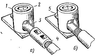
Rice. 11. Connecting an aluminum stranded wire with a cylindrical clamp: a — using the tip of the pin, b — after fusing the end of the thread into a monolith with the addition of alloying additives, 1 — body, 2 — clamping screw, 3 — pin tip, 4 — stranded conductor, 5 — the end of the core, fused into a monolith.
With screw terminals for plug connection, aluminum or copper stranded wires can be connected after breaking with a pin or after fusing the end of the wire into a monolith with the addition of alloying additives.