Installation of the internal grounding loop
 Before the trenches are filled, steel strips or round bars are welded to the external ground loop, which is then driven into the building where the equipment to be grounded is located. There must be at least two inputs connecting the grounding electrodes to the internal grounding network (internal grounding loop) and they are made with steel wires of the same dimensions and cross-sections as connecting the grounding electrodes to each other. As a rule, the entrances of the grounding wire in the building are laid in non-combustible non-metallic pipes, protruding about 10 mm from both sides of the wall.
In the shops of industrial enterprises and buildings of transformer substations, the electrical equipment that needs to be grounded is located in different ways, therefore, to connect it to grounding system in the room, grounding and neutral protective conductors.
As the latter, zero working conductors are used (except for explosive installations), as well as metal structures of the building (columns, trusses, etc.), conductors specially designed for this purpose, metal structures for industrial purposes (frames of switchgear, crane runways, elevator shafts, framed ducts, etc.), steel pipes for electrical wiring, aluminum cable sheaths, metal busbar sheaths, ducts and trays, metal permanently laid pipelines for all purposes (except pipelines of combustible and explosive substances and mixtures), sewerage and central heating).
The use of metal sheaths of cable-carrying pipe conductors, metal hoses, armored and lead sheaths of cables as neutral protective conductors is prohibited, although they themselves must be grounded or neutralized and have reliable connections throughout.
If natural grounding lines cannot be used, then steel wires are used as grounding or neutral protective wires, the minimum dimensions of which are given in the table. 1.
Table 1. Minimum dimensions of grounding wires
Explorer view Place of installation in a building in outdoor installation (OU) and in the ground Round steel Diameter 5 mm Diameter 6 mm Rectangular steel Section 24 mm2, thickness 3 mm Section 48 mm2, thickness 4 mm Angle steel Shelf thickness 2 mm The thickness of shelves is 2.5 mm in NU and 4 mm in ground Steel gas pipe Wall thickness 2.5 mm Wall thickness 2.5 mm in NU and 3.5 mm in ground Thin wall steel pipe Wall thickness 1, 5 mm 2.5 mm in NU, in the ground is not allowed
Grounding conductors in the premises must be accessible for inspection, therefore they (with the exception of steel pipes for hidden electrical conductors, cable sheaths, etc.) are laid in the open.
When installing the internal ground loop, the passage through the walls is carried out in open openings, non-combustible non-metallic pipes, and through the ceilings - in the sections of the same pipes protruding 30-50 mm above the floor. Grounding conductors should be carried out loosely, except in explosive installations, where pipe openings and openings are sealed with light-penetrating non-combustible materials.
Before laying, steel tires are straightened, cleaned and painted on all sides. After welding, the joints are covered with asphalt varnish or oil paint. In dry rooms, nitro enamels can be used, and in rooms with moist and corrosive vapors, paints resistant to chemically active environments should be used.
In rooms and outdoor installations with a non-aggressive environment, in places accessible for inspection and repair, it is allowed to use bolted connections of grounding and neutral protective conductors, provided that measures are taken against their weakening and corrosion of the contact surfaces.
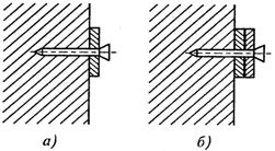
Rice. 1. Attaching grounding wires with dowels directly to the wall (a) and with lining (b)
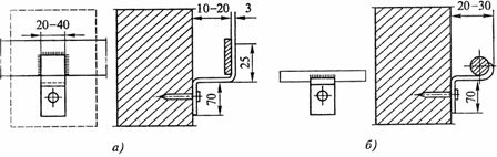
Rice. 2. Fastening of flat (a) and round (b) ground wires using supports
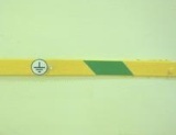
The open earth and neutral protective conductors of the internal earth loop must have a distinctive color: on a green background, yellow stripes 15 mm wide at a distance of 150 mm from each other.Grounding wires are laid horizontally or vertically and at an angle they can only be laid parallel to the inclined structure of the building.
Conductors with a rectangular cross-section are fixed with a wide plane to a brick or concrete wall using a construction and installation gun or a pyrotechnic mandrel. Ground wires are attached to wooden walls with screws. Supports for fixing grounding wires must be installed at the following distances: between supports on straight sections — 600 — 1000 mm, from the tops of the corners at bends — 100 mm, from the floor level of the room — 400 — 600 mm.
In humid, especially humid and rooms with corrosive vapors, it is not allowed to attach grounding wires directly to the walls; they are welded to supports, fixed with dowels or built into the wall.