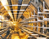
Laying cables in tunnels and collectors
 The construction of cable tunnels and collectors is recommended in cities and enterprises with a densely built-up area or with a high saturation of the territory with underground utilities, as well as in the territories of large metallurgical, machine-building and other enterprises.
Tunnels and manifolds with a circular cross-section have an internal diameter of 2.6 m and are designed for two-sided cable routing.
Cable tunnels and manifolds with a rectangular cross-section are designed for two-sided and one-sided cable laying and are available in through and semi-through versions. With a large number of cables, tunnels and collectors with a rectangular cross-section can be triple-shifted (double).
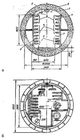
Fig. 1. Laying cables in tunnels and collectors with a circular cross-section: a — tunnel, b — collector; 1 — tunnel block, 2 — cable construction block; 3 — cables over 1 kV; 4 — cables up to 1 kV; 5 — control cables; 6 — connecting sleeve; 7 — free shelf for laying connectors; 8 — lamp; 9 — area of fire detectors and pipelines for mechanized dust removal and fire extinguishing.
Figure 2. shows the placement of cables in rectangular tunnels.
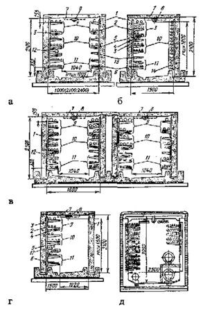 Fig. 2. Laying of cables in tunnels and collectors with a rectangular cross-section: a and b-passage with two-sided arrangement of cables, internal-passage three-walled with four-sided arrangement of cables; d — control point for one-sided arrangement of cables; d-bilateral passage collector; 1 — tunnel block; 2 — trunk; 3 — shelf; 4 — suspension; 5 — fire-resistant barrier; 6 — welded tray; 7 — zone of fire detectors and pipelines for mechanized dust removal and fire extinguishing; 8 — lamp; 9 — power cables over 1 kV; 10 — power cables up to 1 kV; 11 — control cables; 12 — connector in protective case; 13 — shelf for laying the connecting sleeve; 14 — suspension.
The use of half-through tunnels is allowed in places where underground communications interfere with the execution of a through tunnel, while a half-through tunnel is taken with a length of no more than 15 m and for cables with a voltage of no more than 10 kV.
The passages in cable tunnels and collectors must be at least 1 m, but it is allowed to reduce the passages to 800 mm in sections with a length of no more than 500 mm.
The floor of the tunnel or collector must be made with a slope of at least 1% towards the catchments or storm drains. In the absence of a drainage device, drainage wells with a size of 0.4×0.4×0.3 m, covered with metal grids, should be arranged every 25 m. If it is necessary to go from one brand to another, ramps with a slope of no more than 15˚ should be arranged. In the tunnels (collectors), measures must be taken to prevent the penetration of underground and process water into them, and drainage of soil and rainwater must be ensured.
The tunnels (collectors) should primarily be equipped with natural ventilation.The selection of the ventilation system and the calculation of the ventilation devices are made on the basis of the heat release specified in the construction specifications. Ventilation devices should be automatically shut off and air ducts should be equipped with remote or manual dampers to prevent air from entering the manifold or tunnel in the event of a fire.
Stationary means of remote and automatic fire extinguishing must be provided in the tunnel and collector. Cables, cable joints, neglect of fire and flammable materials during installation or repair work can be a source of fire.
Collectors and tunnels should be equipped with electric lighting and a number of portable lamps and instruments.
Long cable tunnels and collectors are divided along their length by fire-resistant partitions into compartments no more than 150 m long with doors in them.
The laying of cables in manifolds and tunnels is calculated taking into account the possibility of additional laying of cables in the amount of at least 15%.
Completed tunnels and collectors must be accepted by the electrical installation and operating organizations before the start of laying cables. Upon acceptance, the compliance of the structure is checked The project, as well as the requirements of PUE and SNiP.
Metal support structures for cables should be installed at a distance of 0.8-1 m from each other on horizontal straight sections. In places where the route turns, the distance between the structures is selected locally, taking into account the permissible bending radius of the cables, but no more than on straight sections. All metal structures must have an anti-corrosion coating.
Before laying cables in structures, representatives of the operating organization check the readiness of the cable laying route:
• fastening of pipes embedded in walls;
• diameter of the pipes and their compliance with the design mark of the cable;
• fastening structures (racks, shelves) and the distance between them horizontally and vertically;
• painting of metal structures (especially in the places of welding);
• lack of water and leakage of water in the pits;
• serviceability of the electrical wiring and the presence of lamps (if necessary, install additional lighting at turns);
• absence of foreign objects along the entire route;
• Linear and corner rollers located along the entire track (corner rollers must be fixed).
After fulfilling the listed requirements, the laying of cables is allowed and a certificate of hidden work and a certificate of acceptance of the structure for the installation of cables are drawn up. Only cables with non-flammable sheaths may be used for laying in tunnels.
For two-sided cable constructions, the control cables should be placed, if possible, on the opposite side of the power cables. In the case of a one-sided arrangement of structures, the control cables must be placed under the power cables and separated by a horizontal partition.
When using automatic fire suppression with air-mechanical foam or water spray, barriers may not be installed.
Power cables with a voltage of up to 1 kV must be laid under cables with a voltage higher than 1 kV and separated by a horizontal barrier.It is recommended to lay different groups of cables, namely working and backup cables with a voltage higher than 1 kV, on different shelves, separated by horizontal fireproof partitions. Pressed unpainted asbestos-cement boards with a thickness of at least 8 mm are recommended as partitions.
Laying of armored cables of all cross-sections and unarmored conductors with a cross-section of 25 mm2 and more should be carried out along structures (racks), and unarmored cables with a conductor cross-section of 16 mm2 or less should be laid on trays, placed on cable structures.
Cables laid in tunnels and manifolds must be securely fastened at the end points, on both sides of bends and connectors. To avoid installing additional bushings, the preferred cable length should be selected face-to-face.
Each connection of the power cables must be laid on a separate shelf of the supporting structures and enclosed in a protective fire jacket, which must be separated from the upper and lower cables along the entire width of the shelves by protective asbestos-cement partitions. the tunnel and channel must provide free rows of shelves for laying connecting connectors.
For the passage of cables through partitions, walls and ceilings, branch pipes made of non-combustible pipes must be installed. In places where cables pass through pipes, the fences in them must be carefully sealed with non-combustible material. The filling material must provide adhesion and be easily destroyed if additional cables are installed or if they are partially replaced.
The use of unarmored cables with a polyethylene sheath in cable tunnels is prohibited under fire safety conditions.
Before laying the cable, it is necessary to measure the length of the cable line in accordance with the project. For laying the cable in extended tunnels, it is also necessary to clarify the location of the places from which the cable can be pulled into the tunnel or collector (wells, ventilation shafts, etc.), determine the actual distance between them
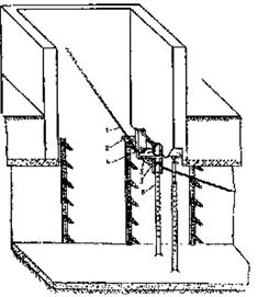
Mechanized rolling of cables in tunnels, as a rule, is carried out by pulling with a winch (Fig. 3).
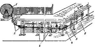
Rice. 3. Cable rolling in the tunnel: 1 — cable drum; 2 — angular rollers; 3 — linear rollers; 4 — corner roller in the bend of the track, 5 — cable; 6 — winch rope
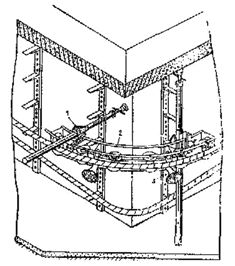
Fig. 4. Installation of a platform with a traction winch at the opening of the ventilation shaft: 1 — winch; 2 — platform; 3 — trunk; 4 — telescopic in the pores, 5 — transverse beam, 6 — ventilation shaft
Rice. 5. Installation of a bypass block for the passage of the rope from the tunnel and the ventilation shaft: 1 — rope; 2 — transverse beam; 3 — tow bar; 4 — axis; 5 — block, 6 — reinforced trunk
During unwinding, the cable drum is mounted on jacks at one end of the track, and at the other end a traction winch. The winch cable is attached to the end of the cable, the cable is pulled along the route, and then manually transferred to the designated location of the cable structures.
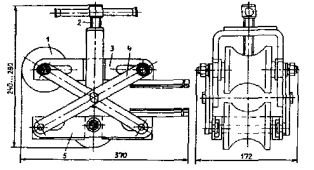
Rice. 6. Installation of a bypass universal device at the angle of rotation of the cable route in the tunnel: 1 — grip; 2 — sector; 3 — support roller
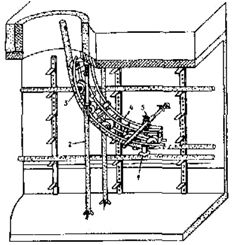
Rice. 7. Installation of a bypass universal device when lowering the cable from the well (ventilation shaft) into the tunnel: 1 — support roller; 2 — telescopic stand; 3 — roller; 4 — sector; 5 — capture
Before rolling, various devices are installed along the track:
• fixed direction of the winch rope (Fig. 4) — when the rope moves from the traction winch drum to the ventilation shaft;
• bypass block for passing the rope from the ventilation shaft (well) and the tunnel at the intersection of the ventilation shaft and the tunnel ceiling (Fig. 5);
• bypass devices under the angles of rotation (fig. 6), at the entry points in the cable tunnel (fig. 7).
In the presence of pipe intersections and construction openings, special devices for introducing the cable into the pipe (Fig. 8) and bypass devices for passing the cable through the openings (Fig. 9) are installed.
Rice. 8. Device for introducing a cable with a voltage of up to 10 kV into pipes: 1 — roller; 2 — screw, 3 — guide; 4 — rocker; 5 — shooting guide
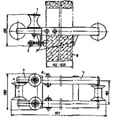
Rice. 9. Bypass device for passing a cable through the holes: 1 — vertical roller, 2 — screw clamp: 3 — frame limiter; 4 — horizontal roller; 5 — fixed frame; 6 — constipation; 7 — movable frame; 8 — wall
Cables laid horizontally along the structures are firmly fixed at the end points, at the bends of the route, on both sides of the cable bend, at the connectors and end connectors and lugs. Cables laid vertically along structures and walls are fixed to each cable structure.
In the places of attachment between unarmored cables with a lead or aluminum sheath, metal supporting structures and a metal bracket, gaskets of elastic material (sheet metal, sheet polyvinyl chloride) with a thickness of at least 1 mm must be placed to protect the sheath from mechanical damage.
Unarmored cables with a plastic sheath can be fixed with clamps (clamps) without seals.The metal armor of the cables laid in the tunnel must have an anti-corrosion coating.