Mechanisms and accessories for lifting, transporting and rigging during electrical installation
Ropes and lifting devices
 Depending on the material, ropes are divided into steel (cables), hemp and cotton. Steel ropes are made in single lay, when the rope is wound directly from wires, and double lay, when the wires are wound into strands and the strands into rope. According to the type of tension of wires and threads, steel ropes are transversely located, in which the directions of tension of wires in threads and threads in a rope are opposite to each other, and unilateral, in which these directions coincide. Crossover cables are less prone to unraveling than unidirectional cables.
Compared to hemp and cotton ropes, steel ropes are more reliable and durable and therefore find predominant use in hoisting and hoisting. Hemp and cotton ropes are used only for wires or for lifting small loads (delivery of tools and accessories, lifting garlands when installing the switchgear busbar, etc.).
The disadvantages of steel cables include their relatively low elasticity (flexibility). The flexibility of the ropes depends on the diameter of the wires: the smaller the diameter of the wires in the strands of the rope, the greater the flexibility of the rope. A rope made of thinner wires wears out faster and is more expensive. Therefore, the choice of ropes should be made depending on their purpose.
Steel ropes are stored in coils or drums in closed dry rooms on wooden lining. Each rope must be provided with a label indicating the type, diameter, length and weight of the rope. Working ropes must be lubricated with rope ointment at the following times: load (roller) — 1 time in 2 months, rope and slings — 1 time in 1.5 months, clamps — 1 time in 3 months. The ropes stored in the warehouse are lubricated once every 6 months.
The selection of ropes for hoisting mechanisms and lifting devices is made according to the value of the actual breaking force of the rope in N (the load at which the rope sample breaks when tested on a tensile testing machine). This effort is usually given in the passport of the rope (certificate). If the actual breaking strength is not indicated in the passport, but the total breaking strength of all individual wires (Rsum), then the actual breaking strength should be taken as 0.83 Rsum.
When working with ropes, it is necessary to monitor the degree of wear and to reject ropes with dangerous wear. The dangerous wear of the rope is determined by the number of broken wires at the laying step (the length of the rope through which the strand makes a complete revolution around its axis).On the section of the rope on which the largest number of broken wires is found, the laying step is noted and the number of breaks is counted on it.
When the wire rope diameter decreases as a result of surface wear or corrosion by more than 40% of the original value, the rope is rejected.
Steel, hemp and cotton ropes, slings of all types and lifting devices must be subjected to periodic checks during operation by the person responsible for their maintenance, as well as pass static load tests.
Slings serve to attach the load to the hook of the lifting mechanism. The slings are made of steel ropes. Depending on the purpose of the slings and the items of electrical equipment to be lifted and installed, slings of different designs are used. The connection of the free end of the cable to the main branch to form a loop of the sling is carried out by a braid. Cable braiding is a complex operation that requires highly skilled contractors and must be performed by special braiding devices.
Selection of standard sling size is made based on weight, configuration and locations of sling equipment and loads. The load on one branch of the sling is determined by the formula S = Q / (n NS cosα),
where S is the load on one branch of the sling, kg, Q is the mass of the lifted load, kg, n — the number of branches of the sling, α — the angle between the vertically lowered axis and the branch of the sling (Fig. 1).
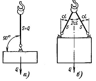
Rice. 1. Schemes for slings with a load
Slings should be chosen so long that the angle between the branches of the sling and the vertical does not exceed 45 °.When lifting, the elements of electrical equipment must be suspended from parts specially designed for this purpose (frames, brackets, mounting loops). In the event that the technical conditions or factory instructions prohibit the exposure of lifting devices (eyes) to tension with a sling at an angle, lifting must be carried out with the help of sleepers (Fig. 2).
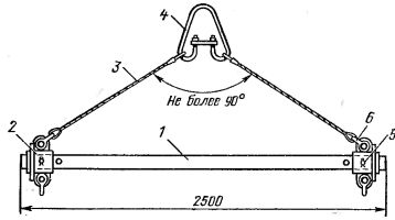
Rice. 2. Traverse for lifting electrical equipment with a load capacity of up to 10 items. 1 — pipe, 2 — connector, 3 — sling with two loops, 4 — detachable suspension (spider), 5 — pin, 6 — straight clamp.
Each belt must be fitted with a token bearing the mark of the belt and the date of its test. Tokens are attached by weaving into a strand of cable during sling manufacture.
Only riggers and electricians who have undergone special training and have a certificate of admission to the production of sling works can be allowed to work on grinding and lifting equipment and other goods. Lifting of critically heavy loads must be done under the direct supervision of a foreman or job maker.
Blocks and rollers
The blocks are used when rigging to change the direction of towing ropes (branching blocks) or as part of chain hoists. Barrier blocks are mainly made with a folding cheek, since in this case there is no need to pull the rope through the block.
The selection of the branch block is carried out according to the formula Q = PK,
where Q is the load capacity of the block, N, P is the force acting on the rope, N, K is the coefficient depending on the angle between the directions of the rope (Fig. 3).
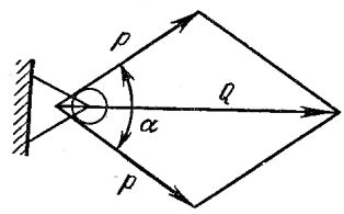
Rice. 3. Forces acting on the segment
The value of the coefficient K is taken depending on the angle α: 0О — 2, 30О — 1.94, 45О — 1.84, 60О — 1.73, 90О — 1.41
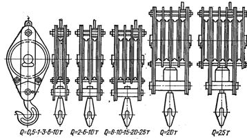
Rice. 4. Blocks
Hoist is used for lifting or horizontal movement of loads, when the traction force required for lifting or moving exceeds the load capacity of the traction mechanism. The polyspast consists of two blocks, movable and fixed, connected to each other by a rope, which is attached to the eye of one of the blocks, alternately bends around the rollers of the two blocks, and the other - with the running end is attached to the traction mechanism.
The magnitude of the force at the end of the rotating rope of the chain hoist is determined by the formula S = 9.8Q /(ηн)
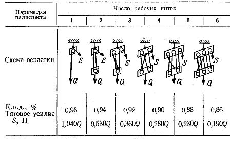
where S is the magnitude of effort, N, Q is the mass of the lifted load, kg, η — c. P. D. Chain hoist, n — the number of chains of the chain hoist. The value of the pulling effort S must not exceed the load capacity of the traction mechanism. The choice of the scheme of the chain hoist depending on the mass of the lifted load and the load capacity of the traction mechanism (tractor, winch) can be made according to table 1.
Efficiency coefficient, schemes and magnitude of polystyrene pulling effort
Winches and hoists
During the operation of winches and hoists, constant supervision of their condition and serviceability of all parts, periodic preventive checks with the elimination of noticed malfunctions and marking of the person responsible for the condition of the winches or hoists in a special newspaper, as well as their periodic testing at least once a year for a special test stand or on an installation site with a static load exceeding the nominal by 25%.Test data must be recorded in a protocol stored in the passport of the mechanism.
A plate showing the date of the test and the date of the subsequent test shall be affixed to the winch or hoist. Winches and hoists that have not passed the next regular test must be taken out of service until the tests are carried out.
Winches are widely used in loading and unloading operations, rigging transformers, switches and other equipment for indoor switchgear, switchboards and busbars for outdoor switchgear. Depending on the type of drive, the winches used for electrical installation are divided into manual, electric and standardized. Hand winches are used in the production of electrical work mainly of two types - drum and lever.
Light drum winches and lever winches are mainly used due to their small size and relatively light weight. Hand winches are recommended for use with a lifting capacity of no more than 3 tons due to their clumsiness, heavy weight and significant effort on the handle of hand winches with a lifting capacity of more than 3 tons.
Hand lever winches work on the principle of pulling a working pulling rope, the rope of which has a clamp. The front handle is mounted on the end of the strap shaft, which is a two-armed lever with a pivot in the middle. To feed the rope into the traction mechanism, move the rope towards the handle. In this case, both pairs of clamps will spread and allow the end of the tow rope to be pushed through the hole in the fitting until it exits the hole in the fastener.
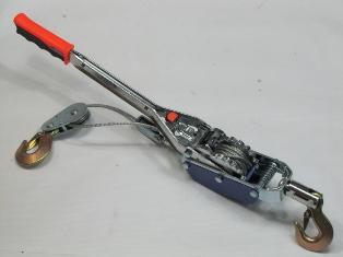
Rice. 5. Hand lever winch
Hand winches are recommended for use when carrying out small amounts of work, in the absence of a power source and in the absence of mechanized lifting devices on site (forklifts, cranes, electric winches).
The electric winch consists of the following main units: frame, drum, gearbox, brake device and electric motor. The motor voltage is 380/220 V. The frame is used to accommodate all winch units on it. The electromagnetically actuated braking device is connected to the electric winch motor and operates automatically when the latter is switched off. The torque is transmitted from the engine to the winch drum through a gearbox. The attachment of the drum to the shaft of the gearbox is carried out by means of a toothed or cam clutch.
The kinematic diagram of the electric winch is shown in fig. 6.
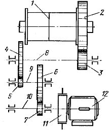
Rice. 6. Kinematic diagram of the electric winch: 1 — drum, 2 — 7 — gearbox gears, 8 — 10 — gearbox shafts, 11 — braking device, 12 — electric motor.
Talu is called a suspended type of elevator with manual or electric drive. Manual hoists are made with worm and tooth gear, they are used for installing reactors in the cells of switchgear indoors, for overhauling and disassembling electric motors, etc. The manual hoist consists of an upper and lower load chain block. The upper block contains a housing, a worm pair including a wheel with a load gear and a worm with a brake device, a traction wheel with an endless chain and an upper hook for suspension. The lower part consists of a cage, a load roller and a lower hook.
The hoist is suspended from the fixed support by the upper hook. When the traction wheel rotates, the worm rotates with the help of a chain, the shaft of which is firmly connected to the traction wheel. The worm drives the worm wheel with the load gear while also selecting the load chain and causing the lower hook and the load suspended from it to rise or fall. Manual hoists with gear transmission are produced with a load capacity of up to 5 tons.
The electric hoist is designed for vertical lifting and lowering, as well as for horizontal movement of loads on a single-rail road on which the hoist moves. The TE type electric hoist consists of two main units: a lifting mechanism and a bogie to which the lifting mechanism is suspended.
The lifting mechanism consists of a body with a drum and an electric motor built into it, a gearbox, an electromagnetic brake and a suspension device (hook block). The brake is applied automatically when the engine is switched off and is released when the engine is switched on.
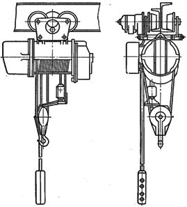
Rice. 7. TE type electric hoist
The undercarriage consists of two cheeks, to one of which are attached two axles with freely rotating wheels, and to the other two drive wheels, on the flanges of which toothed rims are cut. Hoist motors are started by reversible magnetic starters. Control of raising, lowering and horizontal movement to the right or left. Electric hoists are most often used in the premises for large-scale assembly of parts of equipment of blocks and assemblies, as well as for overhauling parts of switches (separating chambers, fire extinguishing chambers) and other equipment in mobile inventory rooms and devices.Electric hoists of the TE type are produced for lifting heights of 6, 12 and 18 m.
Cries
Jacks are mainly used for rigging and installation of power transformers, synchronous compensators and other heavy equipment when these works cannot be done with cranes.
By design, jacks are divided into rack, screw and hydraulic. The rack rack consists of a fixed base 1 with a welded vertical toothed rack 4, a lifting body 3 with a gearbox and a handle 2. The load is lifted on the upper central head or on the lower leg.
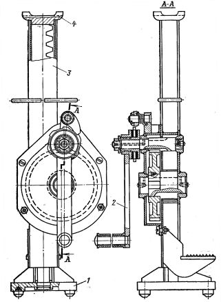
Rice. 8. Jack for trunk
The presence of the lower paw favorably distinguishes the rack jack from other designs, as it allows lifting of loads with a low location of the supporting surfaces. To raise the load, turn the jack handle clockwise. In this case, the rotation is transferred to the gear wheel, which, rolling along the rail 4, lifts the gearbox and the jack housing along with the load along with it.
When the rotational force on the handle is weakened, a special pawl holds the handle through the ratchet disc against reverse rotation under the pressure of the load and thus prevents the load from falling. However, for safety reasons, do not remove your hand from the handle when lifting or lowering a load or while the load remains in the raised position.
A screw jack (Fig. 9) consists of a body 1, a loading screw 2 and a handle 3 with a ratchet, a baton and a retaining rod with a spring. Lifting the load is done by turning the handle counterclockwise.In this case, the loading screw 2 rotates in the fixed internal screw, and the movable screw with the jack head and the weight resting on the head is lifted. When lowering the load, switch the pawl lock and turn the handle in the opposite direction.
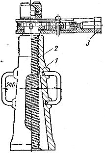
Rice. 9. Screw jack
Hydraulic jack (Fig. 10) consists of housing 1, tank 2 and pump 3. Pump 3 and camshaft 6 are installed in hermetically sealed tank 2. Valve 8 in the housing under piston 4. The piston, rising, lifts the load. to reduce the load, the liquid is returned to the tank. The liquid is filled through the plug 11, and draining is carried out through the plug 5. To fill the tank 2, industrial oil is used.
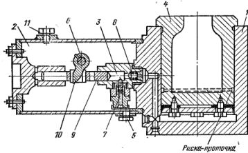
Rice. 10. Hydraulic jack
Telescopic towers and hydraulic lifts
Telescopic towers are mainly used when working on external switchgear busbars. Telescopic towers provide safe working conditions when lifting workers with tools, devices and loads for work at height, and also provide favorable conditions for high-performance work when installing garlands, wires and fittings.
Compared to telescopic towers, hydraulic elevators with articulated boom have the great advantage that their design allows, due to the presence of an articulated boom, to move the cradle with a load in the raised state in any direction without moving the elevator.