Installation of self-supporting insulated wires
 Main use is planned in new and reconstructed lines with a voltage of 0.38 kV insulated self-supporting wires SIP various designs with increased section. Overhead lines with self-supporting insulated conductors are very reliable and require only preventive checks during operation.
Installation technology of the main self-supporting line with SIP2A or Torsada wires.
Installation begins with clearing the route of the future line, while it is necessary to remove trees or large branches that interfere with the installation of supports, rolling and adjusting the wires. It is also necessary to take measures to prevent the contact of the wires with the ground, concrete and metal structures.
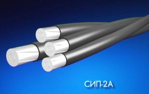
Rice. 1. Construction of self-supporting insulated wire SIP2A
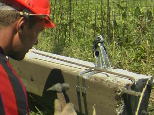
If the line is being reinstalled, it is convenient to fit the mounting brackets to the supports before installing the support. The clamps are attached to the support with a steel strip and clamp using a special device that allows you not only to tighten and fasten the resulting tape clamp, but also to cut off the excess tape.
After fixing the brackets, the support is installed in the required orientation. The installation of self-supporting insulated wires must be carried out in accordance with technological maps or instructions, using special linear fittings, mechanisms, devices and tools at a temperature of at least 20o ° C.
A characteristic feature of the installation is the rolling of the self-supporting insulated wire with the help of rollers and a guide rope. This technology protects the self-supporting insulated wire from mechanical damage during operation, and is also the main condition for maintaining the high performance of the line throughout its service life.
The installation of a self-supporting insulated wire must be carried out in accordance with all safety requirements and organizational and technical measures to ensure the safe performance of work.
With a cross-section of phase conductors up to 50 mm2 on limited sections of lines up to 100 m and a range of up to 50 m, it is allowed to roll a self-supporting insulated wire manually without using rolling mechanisms. We will consider this situation typical for populated areas.
Manual rolling SIP technology provides the following types of work:
1. installation of a drum with a self-supporting insulated wire,
2. connecting the rope and the self-supporting insulated wire,
3. rolling of the guide rope and self-supporting insulated wire on rollers,
4. tensioning and fastening of the self-supporting insulated wire in the anchor section,
5. Fastening of self-supporting insulated wire in supporting brackets.
Installation of a drum with a self-supporting insulated wire
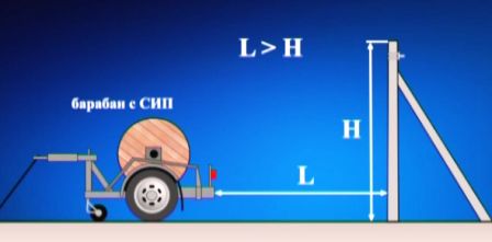
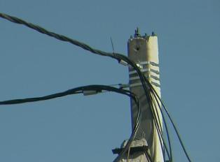
First, a wire drum is installed on one side of the line near the anchor support at a distance of at least its height.A guide rope is attached to the end of the wire using a mounting sock and a swivel. Attached to the first support is a movable pulley mounted on a belt.
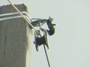
On the remaining supports, the movable hook rollers are suspended from an intermediate support bracket. Simultaneously with the installation of the pulleys, a guide rope is passed through them and then, under the control of one member of the team, a beam of self-supporting insulated wire is pulled. Rolling is carried out without kicks at a speed of no more than 5 km per hour. During rolling, the wire should not touch the ground, metal and concrete structures.
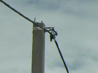
On the finished support of the section, the zero core is attached with an anchor clamp to the anchor clamp. In this case, it is necessary to leave the free end of the bundle with a length sufficient for the subsequent electrical connection of the wires.
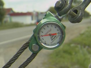
A winch with a dynamometer and a "frog" tube is attached to the first support. According to the assembly tables, the tensile strength of the neutral conductor of the carrier is determined. Visually, the quality of the self-supporting insulation of the insulated wire in the anchor section is assessed by the sagging arrows. After that, it is advisable to leave the wire hanging for a while.
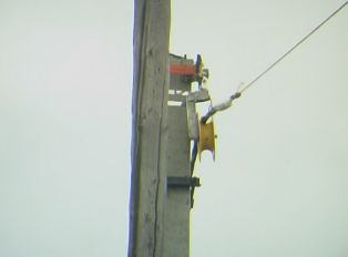
An anchor bracket is attached to the anchor bracket, in which the zero core is fixed. The SIP belt is connected with tightening clamps. After that, the winch is removed, the movable roller is removed, and the ends of the wires of the required length are cut. The self-supporting insulated wire is transferred from the rolling sheave to the supporting bracket mounted on the intermediate support.
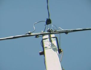
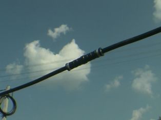
The carrier neutral conductor is separated from the phase conductors with the help of separating wedges, inserted into the recess of the carrier bracket and fixed with a clamp. The movable roller is removed. The wires are fixed with cable ties at a distance of about 15 cm on both sides of the bracket. The middle clamping strip is inserted into the hole in the supporting bracket and fixes the phase wires under the bracket. At this stage, the installation of one part of the line with self-supporting insulated wires can be considered complete.
To connect sections with self-supporting insulated wires in a common line, sealed connecting insulated clamps are used. They provide the necessary mechanical strength and reliable electrical contact.
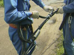
To connect the self-supporting insulated wire using a connection clamp, the insulation is removed from the end of the wire, the bare part of the wire is exposed, and a sealed clamp is placed over it. A hexagonal die is inserted into the hydraulic hand press, the press is closed with a clamping ring and the handle swing is activated. The crimping process is carried out until the die halves are closed. In the same way, another wire is fixed in the bracket.
For the device of branches from the main line to the entrances to the building, anchor clamps with a design similar to the main ones are used. Since the branch uses a self-supporting insulated wire with conductors of equal diameter without a supporting neutral conductor, the entire bundle of two or four conductors is attached to the clamp.
To connect the branch to the line, sealed punching clamps are used, which do not require stripping the insulation from the wires.When the clamp head is tightened, the teeth of the contact plates pierce the insulation of the wires to ensure reliable contact. The dose of clamping force is provided by breaking the calibrated head. A sealed cap is placed on the end of the branch wire.