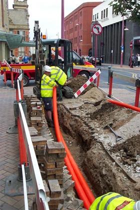
Laying the power cable in the ground
Cable lines are laid in earthen trenches, special cable structures (cable ducts, trays), on overpasses, in galleries, outdoors on the walls of buildings and structures, in pipes, tunnels, etc. The cheapest way to run cables is to put the cables in a trench in the ground.
This method does not require large construction costs, and in addition, good conditions are created for cooling the cables. The disadvantages of this method can be described as 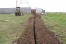 the possibility of mechanical damage to the cables during excavation near the cable route. Cables are laid in trenches at a depth of 0.7 m. No more than 6 cables for voltage 6-10 kV or two cables for 35 kV are laid in one trench. It is allowed to place no more than one bundle of control cables next to them.
The width of the trench along the bottom for one cable is determined by the convenience of the trench and is 0.2 m at voltages up to 10 kV and 0.3 m at 35 kV. The width of the trench from above depends on its depth and the angle of rest of the soil.
1 — communication cable; 2 — brick for protection against mechanical damage; 3 — soft soil for beds (sand); 4 — cables up to 35 kV; 5 — cables to 10 kV; 6 — control cables.
On the territories of energy-intensive industrial enterprises and in the presence of more than 20 cables running in one direction, laying in tunnels is used.
In areas with soil conditions that have a detrimental effect on the cables, in permafrost areas the cables are laid on racks and galleries.
Cables are laid openly on the walls of buildings and structures in cases where the building structures are made of non-combustible material.
The cable ducts are made of prefabricated reinforced concrete channel elements of different widths and heights.
Cable line installation technology
 Cable lines are laid in such a way as to exclude the possibility of dangerous mechanical stresses and damage during operation.
Cables are laid with a small margin in case of possible soil displacements and temperature deformations of the cable itself. In trenches and on hard surfaces inside buildings and structures, the material is created due to the wavy laying of the cable, and for cable structures, the stock is made due to the sag arrow. Storage of cable with rings is not permitted.
Cables laid horizontally on structures, walls, etc. firmly fixed at the end points, at the end connectors and at the bends of the track, on both sides of the bends and at the connectors. In vertical sections, cables are attached to each cable structure. Instead of rigidly attaching unarmored cables to structures, gaskets made of sheet metal or sheet polyvinyl chloride or other elastic material are used.
Indoors and outdoors in places accessible to unqualified personnel, as well as where the movement of vehicles, goods and mechanisms is possible, cables are protected by placing them at a height of at least 2 m from the floor or at a depth of 0.3 m in the ground.
 Installation of cable lines is carried out in two stages. At the first stage, supporting structures are installed in buildings and structures for laying cables. At the second stage, cables are laid and connected to the terminals of the electrical equipment.
The cable is delivered to the place of installation in its original packaging (drums). The transportation of cables is carried out on transporters TKB-6, TKB-10 with a load capacity of 6 and 10 tons. The transporter TKB-6 is moved by car, and TKB-10- with a tractor.
After removing the outer casing of the drum, the condition of the outer turns of the cable is assessed, paying attention to the casing and protective cover, to stains from the impregnating composition, to punctures, cavities, breaks, displacements and gaps between the turns of the armored tapes.
Damaged outer turns of the cable are removed, and its insulation is tested with increased voltage. The paper insulation is checked for moisture before the test. To do this, paper strips adjacent to the sheath and cores are immersed in paraffin, heated to 150 g C. Light cracking and foaming indicates that the cable insulation is wet. In this case, a section of 250 — 300 mm is cut from the end of the cable and a second check is carried out. To avoid mistakes when checking the moisture content of the cable, do not touch the strips with your hands. After testing the cable with increased voltage, the sealing caps at the ends of the cable are restored.
The technical process of laying a cable consists of the following operations:
1.Cable drum assembly.
2. Lifting the drum with jacks.
3. Removing the casing from the drum.
4. Stretching the cable by rotating the drum evenly and pulling the cable along the route to the design position.
In manual cable winding, the cable is pulled by electricians. It is necessary to arrange people in such a way that each of them has a load of no more than 35 kg.
In the cold season, the cables are laid without preheating, if the air temperature was not lower 24 hours before the start of work:
0 g C — for power armored and non-armoured cables with paper insulation in lead or aluminum sheath;
-7 gr C — for control and power cables with a voltage of up to 35 kV with plastic or rubber insulation and sheath with fibrous materials in a protective cover;
— 15 gr C — for control and power cables with a voltage of up to 10 kV with polyvinyl chloride insulation and sheath without fibrous materials in a protective cover;
— 20 g C — for non-armored control and power cables with polyethylene insulation and sheaths without fibrous materials with a protective cover.
Warming of the cables before laying is done indoors. The cable is laid for no more than an hour if the ambient temperature is from 0 to -10 ° C, no more than 40 minutes at a temperature from -10 to -20 ° C and no more than 30 minutes at a temperature below -20 ° C. At an ambient temperature below -40 degrees C, laying of cables of all brands is not allowed.
At a laying temperature below -20 degrees C, the cable is heated with electric current throughout the rolling period according to the scheme.
Conductive conductors on the inner end of the cable; 2 — heated cable; 3 — conductive cores on the outer end of the cable; 4 — current transformer; 5 — transformer; adjustable transformer.
Power cord connection technology
The ends of the cable are cut before the installation of connectors and lugs. It consists in successive staged removal of a certain length of protective covers, armor, casing, screen and insulation. The dimensions of the cuts are determined according to the technical documentation.
Proceeding to cut the cable, check the absence of moisture in the paper insulation and wires. If necessary, remove wet insulation, excess length of cable ends, other defective areas by cutting with sector scissors.
Cutting the cable begins with determining the places to place the strips, which are calculated according to the formula: A = B + O + P + I + G.
1 — external cover; 2 — armor; 3 — shell; 4 — belt insulation; 5 — wire insulation; 6 — cable core; 7 — bandage; A, B, I, O, P, D — channel dimensions.
At the end of the cable, measure distance A and straighten this section. The resin strip is then rolled up and a bandage applied. It can be made from galvanized steel wire. The ends of the wire are gripped with pliers, twisted and bent along the cable.
The outer cover of the cable is screwed to the installed strip, but is not cut off, but left to protect the bumper from corrosion after the connector is installed. A second bandage is placed on the cable shield (B) at a distance B (50 — 70 mm) from the first wire bandage. Along the outer edge of the bandage, the strips of armor are cut with a hacksaw, after which this armor is unwound, broken off and removed.
To remove the shell (O) at a distance (50 — 70 mm) from the armor cut, annular cuts are made not half the depth. An incision is made with a special knife with a cut depth limiter and the sheath is removed. In addition, the cores of the cables are freed from the insulation of the belt and bent on a template. After that, a place is prepared for connecting the ground.
To connect the cable cores to the contact terminals of electrical devices, they are terminated with lugs fixed to the core by crimping, welding or soldering. Termination of solid wires can be done by forming a lug from the end of the wire.