How to properly install and align the engine
Mounting the electric motor
The electric motor, delivered to the installation site by the manufacturer or from the warehouse where it was stored before installation, or from the workshop after the revision, is installed on a prepared base.
As bases for electric motors, they are used depending on the conditions: cast iron or steel plates, welded metal frames, clamps, sliders, etc. Plates, frames or slides are aligned axially and in a horizontal plane and fixed on concrete foundations, ceilings, etc. using foundation bolts that are embedded in prepared holes. These holes are usually left when concreting foundations, by previously placing wooden plugs in the corresponding places.
Shallow holes can also be drilled into precast concrete foundations using electric and pneumatic hammers equipped with high-performance tools with carbide tips. Holes in the motor mounting plate or frame are usually made at the factory, which provides a common plate or frame for the motor and drive mechanism.
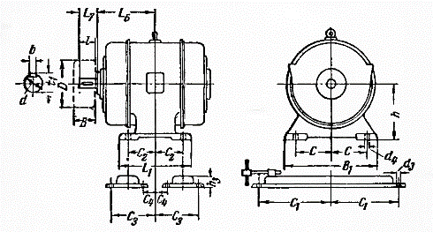
If there are no holes for the electric motor, the base is marked at the installation site and the holes are drilled. To carry out these works, the installation and mounting dimensions of the installed electric motor are determined (see figure), namely: the distance between the vertical axis of the motor and the end of the shaft L6 + L7 or the end of the mounted half-coupling, the distance between the ends of the half-couplings on the shafts of the electric motor and the mechanism driven by it, the distance between the holes in the legs along the axis of the electric motor C2 + C2, the distance between the holes in the legs in the perpendicular direction C + C.
In addition, the shaft height (axis height) of the mechanism and the motor axis height h must be measured. As a result of the last two measurements, the thickness of the foot pads is determined in advance.

Rice. Designations of the engine mounting dimensions.
For convenience when centering the electric motor, the thickness of the pads should be ensured within 2 — 5 mm. Lifting of electric motors to the foundations is done with cranes, hoists, winches and other mechanisms. Lifting of electric motors weighing up to 80 kg in the absence of mechanisms can be done manually using decks and other devices. The electric motor mounted on the base is pre-centered with a rough fit along the axes and in the horizontal plane. Final alignment is done when the shafts are connected.
Engine alignment
The electric motor, mounted on a support structure, is centered relative to the shaft of the mechanism it rotates. Alignment methods are different depending on the type of transmission.The reliability of the operation of the electric motor and mainly its bearings depends on the accuracy of the alignment.
Belt
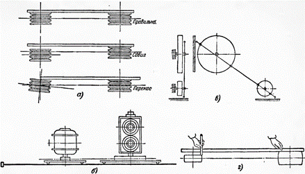
In belt and wedge transmissions, a prerequisite for the correct operation of the electric motor with the mechanism driven by it is compliance with the parallelism of their shafts, as well as the coincidence of the middle lines (in width) of the rollers, because otherwise the belt will jump. Alignment is carried out with a distance between the centers of the shafts up to 1.5 m and with the same width of the rollers using a steel ruler for alignment.
The ruler is applied to the ends of the rollers and the electric motor or mechanism is adjusted so that the ruler touches two rollers at four points.
When the distance between the axes of the shafts is more than 1.5 m, as well as in the absence of an alignment ruler of a suitable length, the alignment of the electric motor with the mechanism is carried out using temporarily installed clamps and clamp rollers. The adjustment is made to achieve the same distance from the clamps to the string. The shafts can be aligned with a thin cord drawn from one roller to the other.
The alignment of the electric motor and the machine with rollers of different widths is done based on the condition of equal distance from the center lines of the two rollers to the string, lace or ruler for alignment.
The calibrated electric motor must be firmly fixed with a subsequent check of the accuracy of the alignment, which can be accidentally broken when fixing the electric motor.

Alignment of shafts with V-belts and V-belts. a — with the help of an ambulance; b — use of a stapler and strings; c — using lace; d — using a ruler with rollers of different widths.
Direct connection with connectors.
The alignment of the motor with the mechanism is necessary to achieve such a mutual position of the shafts of the motor and the mechanism, in which the values of the clearances between the coupling halves will be equal. This is achieved by moving the engine over short distances in the horizontal and vertical planes.
Before centering, the tightness of the fit of the half-couplings on the shafts is checked by tapping the half-coupling, while at the same time feeling the connection of the half-coupling with the shaft by hand.
Centering is carried out in two stages: first, preliminary — using a ruler or steel square, and then final — using centering clamps.
Preliminary alignment is performed by checking the absence of a gap between the edge of the applied ruler (steel square) and the one forming both half couplings. This check is done in four places: top, bottom, right and left.
In all cases, when aligning, attention is paid to the fact that the number of individual spacers under the feet of the electric motors is as small as possible; thin pads with a thickness of 0.5 — 0.8 mm are used no more than 3 — 4 pieces.
If, according to the centering conditions, there are more of them, they are replaced with a general seal of greater thickness. A large number of spacers, and even more so from thin sheets, do not provide reliable fastening of the electric motor and can cause misalignment; it also presents an inconvenience for subsequent repairs and alignment during operation.
