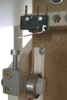
Installation of limit switches and micro switches
 Limit switches, switches or their elements can be installed in any plane and at any angle on the external walls and recesses of the machine, under the housings of the machine mechanisms, in the housings of the devices of which they are an integral part. When installed, they provide easy installation and maintenance, excluding the harmful effect of the external environment (metal dust, shavings, oil, etc.) on the switch.
The normal operation of the switch under the action of the hard stop is ensured by the spring of the switch, which compensates for the excess movement of the stop. The largest angle of inclination of the direction of force from the sliding or cam stop to the axis of the pin or lever with a roller is not more than 45 °.
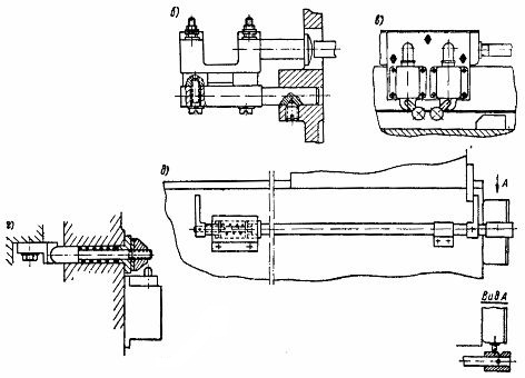
Micro switches have very little pin travel and do not provide the necessary compensation for the travel inaccuracy of the pressure device. In order to increase the accuracy of the operation of the microswitch, a compensating spring must be provided in the design of the pressure device (Fig. 1).
Pressing devices can be done in two ways:
1) the switch is pressed when the brake is moving,
2) the initial position of the switch is pressed, the switch is actuated when the stop is retracted.
The latter method increases the reliability of operation of devices with microswitches.
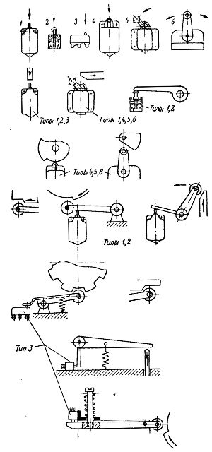 Rice. 1. Examples of pressure devices for limit switches.
Travel switches are used:
-
when movement stops for moving machine parts,
-
for track management and automation of elementary cycles along the road,
-
for control and automation of auxiliary drives,
-
as components of selective and preselective control devices,
-
as executive contact elements of some electrical and electro-hydraulic control devices.
The limit switches, used as travel brakes, are located mainly on the outer walls of the machine. Installing motion limiters at the edges of the fixed bed (Fig. 2, a) is less convenient for installing wiring than installing them next to each other (Fig. 2, b). In the second case, you can replace two limit switches with one three-position switch (Fig. 2, c).
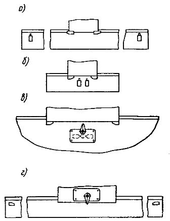
Rice. 2. Methods of fitting travel restraints.
This installation is possible only if the length of the movable part is greater than the length of the stroke. When you install the switches on the bed under the guides, oil can get into the switch housing.In cases where there are other elements of electrical equipment on the movable part of the bed, it is recommended to install limit switches on the same movable part and fix the limiters to the bed (Fig. 2, d).
The fastening of the direction switches, as a rule, is shown on the wiring drawings, and the installation of stops for them is shown on the assembly drawings of the corresponding units. In some cases, for example, when interacting with the mechanisms or devices of the machine, limit switches are depicted on the assembly drawings of the corresponding devices. The coordinates of the position of the knuckle acting on the lever with the roller of the click switch depend on the shape of the knuckle, the diameter of the roller, the length of the lever, its initial position and the size of the working stroke (Fig. 3, a).
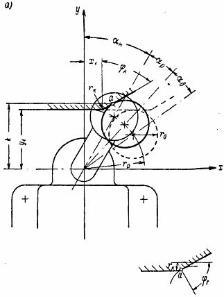
Rice. 3. Interaction of switches and stops: a — the position of the stop at the time of actuation of the switch, b, c — examples of compensating the position of the switch relative to the brake, d, e — examples of conversion of the braking stroke.
In nodal mounting of switches and brakes, it is necessary to provide for compensation of their mutual position to ensure operation without pinching, slipping or incomplete pressing.
Compensation of the position of the switch relative to the limiter is convenient when it is installed, for example, in a distribution box, i.e. there are no rigid fixed mounting connections (Fig. 3, b, c).
If the direct action of the stop is not feasible, apply a stop stroke conversion.For example, if you are on the bed, it is not possible to place limit switches in the plane of the sled, both switches can be bring it to the end of the bed and transfer the action of the sled brakes through the end stop bar.
If a slider with stops is placed in a housing, on the outer wall of which there are switches, the latter are actuated by intermediate stops (Fig. 3, d). It is also possible to convert the actuation of a mechanical overload clutch to act on a travel switch. This makes it possible to turn off the electric drive not only through the travel brakes in the end positions of the moving body, but also in case of sudden overload in intermediate positions.