Mast transformer substations: device characteristics and installation
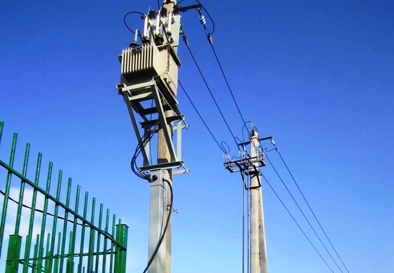
In the power supply of private houses, small cottage settlements and rural areas, mast transformer substations (MTP) are widely used. The specificity of such substations is the placement of equipment on A- and U-shaped structures, which are reinforced concrete or wooden supports with a support platform.
The popularity of mast transformer substations is facilitated not only by the specifics of the power supply, but also by sufficient compactness, safety and less likelihood of external access to conductive elements.
One of the advantages of mast transformer substation compared to conventional KTP — no need to install additional fences. The exception is the poles, which are mandatory when the mast substation is located near the roadway.
In theory, the protection of the substation from fools, reckless people and careless residents is provided by PUE (clause 4.2.125), according to which the vertical distance from the ground (roughly speaking, from the base of the support) to non-insulated conductive parts should be the most - a little 3.5 m.
What are mast transformer substations
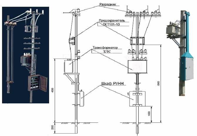
The mast transformer substation kit includes high and low voltage units (RU), rated power transformer, limiters and pin insulators for two voltage levels, a set of mounting parts (including service platform and KTPM frame) and a documentation package.
Additional equipment of KTPM (for example, with certain models of meters), changing the number of connections on the lower side of the substation is possible in agreement with the manufacturer.
Mast substations embedded in power lines must be built on anchor or end supports (this requirement does not apply to single column substations.
When installing a mast substation, the following conditions must be met:
-
the number of installed transformers — 1;
-
the highest permissible voltage — 35 kV;
-
the highest power of the transformer — 100 kVA;
-
the construction of the ladder for climbing to the platform is collapsible, in the folded position in close proximity to the ladder, lockable;
-
connection of the transformer to the high-voltage network - by means of fuses and a three-pole disconnector controlled by the earth;
-
the low voltage shield must be enclosed in a cabinet;
-
a circuit breaker or circuit breaker must be installed to disconnect the transformer from the low voltage side.
-
the connections between the transformer and the shield, as well as between the shield and the overhead lines, must be made with wires with insulation for an operating voltage of at least 1000 V and must be protected from mechanical damage (pipe, channel).
Features of the installation of mast transformer substations
Before starting installation work, you must make sure that there is no damage to the equipment and accessories. Any non-conformity of the KTPM elements with the declared characteristics must be documented (with subsequent notification to the supplier).
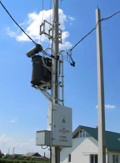
At the first stage of the installation work, the RUNN cabinet is installed on a frame, which in turn is attached to the supports and holds the entire MTP structure.
The connection between the frame and the switchgear is bolted. The holes in the back wall of the cabinet and the holes in the frame must be provided by the manufacturer.
After the low-voltage switchgear is fixed on the frame, the structure is attached by welding, bolts, clamps (depending on the design of the MTP and the manufacturer's instructions) to the support posts.
In the same way, the LVDU using a bolted connection to the frame is connected to the UVN (high voltage side device), with the difference that the holes for fasteners are located on the bottom wall of the cabinet.
Attached to the frame last power transformer (bolted connection) and transformer housing (if provided by the manufacturer).
The connection of the transformer to the terminals is standard: on the high side — through busbars, on the lower side — through a cable jumper.
The transformer case and MTP equipment must be fault-free earthed. Earthing is carried out according to PUE requirements (Chapter 1.7).
We draw your attention to the fact that it is strictly forbidden to lift and fasten to the racks a structure with UVN and an oil transformer previously fixed on it. This can easily damage the equipment or loosen the bolts. In addition, the lugs designed to lift each part of the KTPM are not designed for the total weight of the substation. Why risk expensive equipment and worker health again?
Of course, there are those who like to deviate from the standards and put MTP without complying with PUE requirements. There are extreme athletes who definitely need to get on the supports. Power supply organizations strongly recommend that you follow the rules of electrical safety and, if necessary, carry out work on the installation of electrical equipment, contact only specialized specialists.
100 kV mast transformer substation type MTP • A
The structure of the symbol MTP-100 /35 / 0.4-96 U1:
- MTP — mast transformer substation;
- 100 — transformer power, kV • A;
- 35 — voltage class of the transformer, kV;
- 0.4 — nominal voltage on the LV side, kV;
- 96 — year of development;
- U1 — climate modification and placement category according to GOST 15150-69.
Schematic of MTP mast transformer substation:
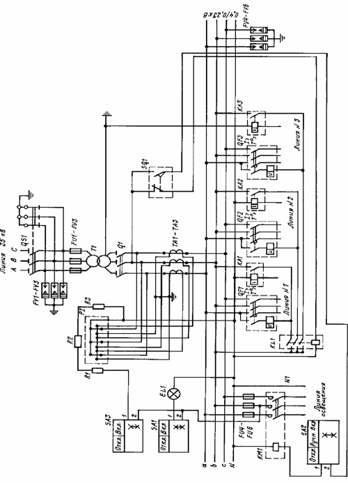
To protect the power transformer from phase-phase short circuit, fuses FU1-FU3 are installed. Atmospheric surge protection is provided by valves FV1 -FV3 — on the 35 kV side and FV4 -FV6 — on the 0.4 kV side.
Active energy is measured by P1 meter.For local heating of the meter, to ensure its reliable operation at temperatures below 0 ° C, resistors R1-R3 are used, which are turned on via switch SA3. Protection against single-phase short circuits of 0.4 kV outgoing lines is provided by current relays KA1-KA3, which, when actuated, turn off the circuit breaker of the damaged line.
Protection against short circuit and overload of 0.4 kV output lines is provided by circuit breakers QF1-QF3.
The presence of voltage and the illumination of the LV switchboard is controlled by the lamp EL1, turned on by the switch SA1. MTP has locks that prevent:
1) switching on the earthing blades of the disconnector when the main blades are switched on;
2) switching on the main blades of the disconnector when the earthing blades are switched on;
3) disconnection of the load currents by the switch Q1.
Blocking according to points 1 and 2 is ensured by the design of the disconnector. 3 Interlocking according to claim 3 is provided by the limit switch SQ1, through the contacts of which the magnetic starter KM1 and the circuit breakers QF1-QF3 are switched off, because according to the design of the MTP, access to the circuit breaker Q1 is only possible when the protection panel is open, as a result of which actuates limit switch SQ1.
The substation has the following main components:
-
external power transformer;
-
low voltage side switchgear (LVSN);
-
high voltage fuses, limiters and motorized disconnector.
The substation is connected to the 35 kV power line using a disconnector that is installed on the support of the power line closest to the MTP. The disconnector has fixed earth blades on the side of the MTP.
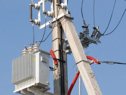
The MTP components (high voltage fuses, arresters, LV switchgear cabinet, power transformer) are placed on the support according to the standard design. The low voltage equipment is located in the LV switchgear cabinet.
Holes with gaskets are provided for bringing out wires in the cabinet for LV switchgear. The wires coming out of the LV distribution cabinet and serving to connect to the 0.4 kV overhead lines and to the power transformer on the LV side are laid in pipes fixed to the support. The RUNN cabinet closes with a door with a self-locking lock.
There is a latch on the door to secure it in the open position. The door is suitable for sealing. A rubber gasket and retaining handles are used to seal the RUNN cabinet door. The handle brackets have holes that allow you to lock the door with padlocks. On the back wall of the LV switchgear cabinet and on the transformer tank, connection plates to the earthing device are welded.