Installation of electrical panels and control panels
Switchboard — a metal structure in the form of a cabinet or panel, designed to accommodate technical automation equipment on it, allowing remote monitoring and control of the technological process.
Cabinets (cabinets) — these are closed devices installed both in special control rooms or similar rooms, and directly in the production room.
Panel boards - open devices - are installed in specialized premises (in distribution points, so-called (RP), protected from dust with limited access for service personnel with appropriate qualifications).
Remote — a closed metal structure in the form of a table of a special shape, on which the technical means for remote control and management are located.
In the presence of a large number of equipment, an alarm shield with a mnemonic diagram of the controlled process is added to the console. This shield can be placed directly in front of the console or installed at some distance from it.
A mnemonic diagram is a simplified graphic diagram of a technological process in a formalized form. Light signaling fittings are built into this circuit.
Panels and control panels can be single-panel, single-chamber, as well as multi-panel and multi-cabinet. Their spatial arrangement depends on the specific conditions of the production process, the number and type of automation equipment, the convenience and safety of their maintenance.
The measuring devices, regulators, signal light equipment, switches, etc. are placed on the front of shields that do not have a remote control. The equipment of the boards and consoles is located in the order of passage through all operations of the technological process.
Basic work during the installation of an electrical panel or control panel
During the installation of the panels, the following work is carried out:
1. Transporting panels to the installation site.
2. Unpacking.
3. Installation of metal structures on the shield.
4. Shina.
5. Installation of devices and devices.
6. Installation of wires on the panels.
7. Installation of control cables.
8. Wiring and connection of wires and cores of the control cables.
The panels are usually connected at the factory. However, even at the panel installation site, the electrician often has to install wires on the panels. This is due to changes made to the installation project caused by new requirements, replacement of equipment and other reasons.
The panels are transported in an upright position. For the convenience of transporting and lifting individual panels from blocks, the plant equips them with inventory bodies.Inventory bodies of freestanding panels and blocks are dismantled after their final installation, and previously shipped panels and blocks are dismantled.
The panels are transported in accordance with the assembly sequence. Secondary devices and devices supplied separately from the panels do not supply power to the shield until after the installation of the panels is complete.
The panels must be unpacked in closed rooms after completion of all construction work at the place of their installation. When unpacking, it is necessary to carefully, without sharp blows, open the box, release the panel from the fasteners to the bottom of the box, remove the protective cover and other packaging materials, check and clean the external external surfaces from dust and packaging material residues.
When installing panels above the cable ducts, special structures must be provided at the base of the building, on which they are installed and fixed at 3 — 4 points.
The elements of the shield are arranged according to the project, they are aligned in horizontal and vertical surfaces.
Mounting tires in control panels
Before installing the tires, you should carefully study the drawing of their location and the packaging documentation. According to the drawing, the location of each tire is determined and placed at the installation site. The ends of the tires and the places where they are fixed in the holders are thoroughly cleaned and lubricated with a thin layer of petroleum jelly.
Tire racks are assembled on special rails. Install rails with rail holders on top of panel end walls. The handles are then placed, checked and finally fixed in the holders.
After the tires are fixed, they are painted. If the tires come from the factory painted and the paint is well preserved, they are not painted.
After the installation is completed, the insulation resistance of the busbars is measured with a megohmmeter for a voltage of 1000 or 2500 V. Then the wires from the section switches and the control cables from the DC board and the central alarm panels are connected to the busbars. Do not connect wires from protection and control panels to busbars. They are connected by the installer after a final installation check.
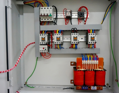
Installation of secondary devices, devices and shield design details
Apparatus, devices and details of the shield design are placed on the shield panels. The former include control switches, switches, relays, circuit breakers, fuses, contact pads; to the second — signaling and electrical measuring devices. The design details are the elements of the mnemonic scheme, inscription frames, upper letters, etc. Before proceeding with the installation of these elements on the panels, the locations and types of these elements should be established according to the drawings.
Devices and apparatus must be carefully inspected and the presence of contact and fasteners must be checked.
Electrical meters and relays should be given to the installer for inspection and adjustment.
Devices and devices have different ways of installation and fixation on the panel, as well as different ways of connecting wires to them. Devices and devices installed on the front side of the panel can be divided into three groups according to the connection method.
Panel mounting of back-connected devices and electrical devices
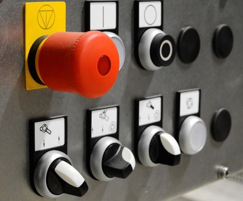
The first group includes devices and devices with a back connection only. These include meter panels, control switches and buttons, signal lamp fittings, light panels, signal indicator devices, etc. These devices are characterized by the fact that their terminals, the wires connected to them, do not pass through the panel and are at a sufficient distance from the panel. Therefore, accidental short circuits of the box are practically excluded.
Panel mounting of devices and electrical devices with front connection
The second small group consists of forward-only devices. This group includes, for example, electricity meters. To connect them, the wires must be passed through a panel in which a window has been cut or holes have been drilled. In these cases, measures should be taken to prevent a short circuit with the panel's case. For this, the windows are framed with a frame made of insulating material, and the insulation of the wires is strengthened by placing pipes of insulating material on them.
When connecting wires to these devices, you must be very careful, as there is no clarity and the probability of a wrong connection increases.
Panel mounting of devices and electrical devices with front and rear connection
The third group, the most extensive, includes devices and devices designed for both front and rear connection. When installing them with a front link, use the same techniques as for the first group.
When installing with a rear connection, it is necessary to provide insulation for the studs and pegs passing through the panel holes.For this purpose, pipes of insulating material are placed on the pins and pegs.
Appliances and devices are installed in pre-prepared holes and fixed with brackets, pins or screws to the panel.
Tools and apparatus must be installed together. One electrician (senior) is located at the front of the panel and controls the correct installation of the device, and the second is behind the panel and fixes this device.
Installation of electrical panel design details
Installing shield design details is easy. The attached letters are fixed on the panel by gluing. The overhead elements of the mnemonic scheme are fixed with screws, pins or glued.
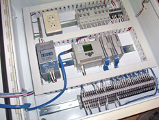
Installation of wires on panels of panels
Typically, factories produce pre-assembled panel panels. However, when installing secondary units, wiring must be done on factory replacement panels or fully field supplied panels.
There are the following ways of mounting wires on panels:
1) with rigid attachment of wires to the panel;
2) on perforated profiles and tracks;
3) air bags without attaching wires to the panel;
4) in boxes.
The last two methods are the most progressive, they are the most common.
The first method with a rigid attachment of wires to the panel is now almost not used, so we will not consider it. In your practice you may encounter this type of attachment.
Laying wires on perforated profiles and tracks
This method of laying wires refers to the type of installation with a rigid installation, but the basis is not a panel, but perforated profiles or tracks.The conductors are laid on gaskets of electrical cardboard or varnished cloth, separating the conductor flows from the metal perforated base. They are attached to the base with buckles. Together, the fasteners add additional insulation to the wire flow.
Perforated profiles are used in places with flexible connections (for example, in places of transitions of wire flows from fixed panels to movable ones) and are attached to the panel by electric welding.
On the perforated tracks, open single-layer laying of wide streams of wires is carried out. Perforated rails are very cheap because they are made from waste from factories that use large quantities of perforated sheet metal for products. Wires can be run on rails separate from panels in workshops. At the installation site, it remains to carry out the installation, that is, to hang the finished wire flows installed on the perforated tracks.
Laying wires with airbags
This installation method belongs to the free wiring category. It is often used when installing short flows (when installing wires, jumpers between devices and devices nearby on panels, when distributing wires and cores of control cables).
Laying wires with airbags eliminates the laborious work of marking and drilling panels, creating savings in the consumption of electrical cardboard and varnished cloth. Since the airbag has insufficient stiffness to overcome this drawback, the wire bundles are assembled around steel rods or attached to stretched lengths of steel wire (strings).
On short sections, the installation of wires with airbags consists of unwinding the wires from the coil and straightening them, measuring and cutting the wires to the required length, assembling the cut wires into a rectangular, more often round package, securing it with temporary strips of insulation tape, securing the wires in the package and removing temporary bandages. The wires in the package are secured with mounting tape with buttons.
To form long bundles of wires on a steel rod, you must first make a frame of steel rod with diameters of 5 — 6 mm. This frame is insulated with two layers of varnished cloth. The gathered wires are laid around the frame so as to form a circular bag and secured with buckle strips.