Installation of electrical panels and control panels of automation devices
By arrangement, electrical panels and control panels can be:
-
operational, from which the management and control of the technological process is carried out;
-
non-working, intended only for the installation of apparatus, tools and devices that are not directly used for control and monitoring of the technological process;
-
combined, which can perform both operational and non-operational functions.
By design, electrical panels can be:
-
external or internal installation;
-
floor and hinged;
-
metal and plastic;
-
one-, two- and multi-section cabinet;
-
with front, back and double doors.
For modern automation systems, taking into account the use of microcontrollers, all control equipment can be placed in hinged one-sided small cabinets, and non-working equipment - in plastic modular screens.

For the installation of circuit boards and control panels, it is necessary to have a circuit diagram, a general drawing with a list of all elements, including mounting accessories.
When assembling automation equipment on boards and consoles, it is necessary to take into account:
-
purpose and number of devices and devices;
-
ease of installation and operation;
-
aesthetic aspects of appearance;
-
service safety.
Almost all modern devices and the devices are designed to be mounted on a DIN rail that is mounted on the rear wall of the cabinet, on a special mounting panel or behind racks on the side walls of the cabinet. This fastening is quite reliable and allows you to quickly and easily install or remove the device.
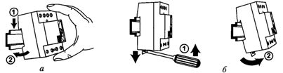
Rice. 1. DIN rail and installation of an electrical device on it: a — installation; 6 — dismantling
The configuration and dimensions of the DIN rails are given in the standard IEC 60947-7-2.
Usually, in the DIN rail cabinet, connecting terminals are also installed, united by standard sizes depending on the cross-section of the wires to be connected. They are intended both for connecting external wires and for connecting devices located on different panels of the cabinet (for example, on the door).
The range of manufactured terminal connections is very extensive both in terms of design (screw, spring, for quick installation, single and multi-stage, etc.) and in terms of electrical parameters (clamping cross-section from 0.14 to 240 mm2, current up to 400 A and voltage up to 1000 V).
In fig. 2 shows the most common terminals that are attached to each DIN rail configuration: a screw (a), a spring (b), a quick-fit (c) and a grounding screw, painted yellow-green (d), which are used to connect protective neutral PE wires.
If the project does not provide for separate control panels, then the following are arranged on the front panels or front doors of the control cabinets:
-
measuring and control devices;
-
light signaling equipment;
-
operational equipment (buttons, keys, etc.);
-
mnemonic schemes.
The listed devices are arranged by functional groups, usually in the order of technological process.
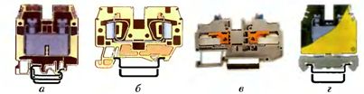
Rice. 2. Types of terminal connections: a — screw; b — spring; c — for quick connection; d — grounding screw
For floor-standing control cabinets, the recommended mounting height of the control equipment is (in mm from the floor to the bottom edge of the device):
-
indicator devices and signaling equipment: 950 — 1800;
-
recording and recording devices: 110 — 1700;
-
operational management equipment: 800 — 1600;
-
mnemonic charts: 1000-1900.
The lower limit is preferable. The same values must be observed when installing a wall-mounted control cabinet directly in the facility.
Devices and devices are connected to each other in accordance with the connection scheme. According to SNiP 3.05.07-85, the connection of single-core copper wires of wires and cables with a cross section of 0.5 and 0.75 mm2 and multi-core copper wires with a cross section of 0.35, 0.5 and 0.75 mm2 to devices and devices, the clamps should, as a rule, be done by soldering, if the design of their terminals allows this to be done. If copper wires with the specified cross-sections are attached to devices that have connection terminals under a screw or bolt, then the wires of these wires and cables must be terminated with a clip.
In fig.3 shows the different types of cable lugs selected depending on the structure of the terminals of the connected device and the lug crimping tool.
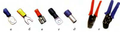
Rice. 3. Structures of cable lugs and a tool for their pressing: a — ring; b — fork: c — for quick connection; g — power; d — tubular; e — pressing tool
Single-wire copper conductors of wires and cables with a section of 1.0; 1.5; 2.5; 4.0 mm2 can be connected directly under a screw or bolt, and multi-core wires with the same or larger cross-section — using lugs.
Each end of the wire or core of the cable at the point of connection to the device or device must be numbered with the circuit number in accordance with the circuit diagram.
The simplest method of marking is to apply the number with a marker (a special felt-tip pen) on a piece of PVC pipe that is placed over the end of the wire before connecting it to the device.
A more progressive method is the use of a holder that is clamped to the connected wire and in which a plate is placed with an attached designation of the electrical circuit (Fig. 4, a). The same figure (Fig. 4, b) shows marking rings that allow standard or individual marking of terminals in one row.
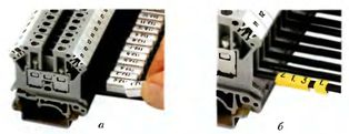
Rice. 4. Modern methods of marking electrical circuits during installation: a — using a fastener holder; b — using marking rings
In the past, bonding wires were connected with raw strands and other tape insulation materials. This technology is time-consuming, unaesthetic and causes inconvenience during setup and repair (to replace the wire, it was necessary to cut the entire harness).
The listed disadvantages are completely eliminated when using perforated boxes (Fig. 5, a), installed along the perimeter of the mounting plane and between the rows of devices. In this case, the installation is carried out without laying the wires, and after its completion, the boxes are closed with lids, which makes the view inside the cabinet more aesthetic. To combine the wires of the interpanel flexible connection (for example, between the inner panel of the cabinet and the equipment of the door), a spiral tube is used (Fig. 5, b).
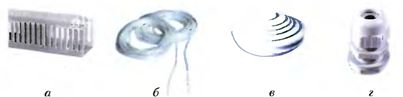
Rice. 5. Installation accessories used in the installation of cabinets and consoles: perforated box; b — spiral tube; c — sealant; d — cable clamp
Depending on the place of installation and the corresponding degree of protection (IP), cabinets and automation panels must be equipped with input devices of the appropriate type.
So, for ordinary rooms, it is enough to install a rubber gasket on the outlet side of the cabinet (Fig. 5, c), in which a hole is cut for the supplied pipe with a minus tolerance. For more difficult working conditions, special cable ends are used (fig. 5, d). The entire structure of the cabinet in terms of IP protection must meet the same conditions.
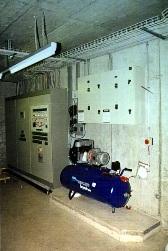
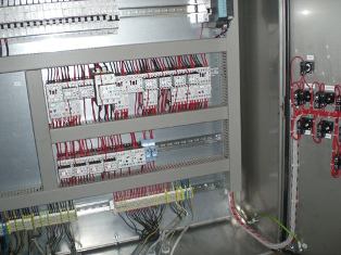
Figure 6 shows general views of the ventilation and air conditioning control panels (with doors removed).
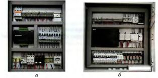
Rice. 6. General view of the control panels of the ventilation and air conditioning system
Panels and consoles are installed on the facility after completion of all construction and basic finishing works, construction of cable channels, openings for the entry of cables and pipes, foundations and built-in metal structures.
 The conditions for installing shields and brackets are determined by projects, but there are several general requirements provided for in SNiP 3.05.07-85:
-
the full-size cabinet and panel boards are installed only on load-bearing steel frames or on a concrete (brick) base;
-
small-sized cabinets and modular shields are usually installed on columns, walls, in openings and other building structures (hinged installation) or on the floor of tinctures; fastening is carried out using bolts, the holes for which are located on the back wall of the cabinet;
-
the spatial position of shields and cabinets must be strictly vertical and horizontal;
-
in the presence of vibrations at the place of installation of shields and consoles, special damping devices must be used;
-
the floors in the room where the boards and consoles are located must not be electrically conductive;
-
electrical wiring in shields and consoles is usually done from below through rubber seals;
-
enclosures with metal shields and brackets are subject to mandatory grounding.
Bondar E. S. Automation of ventilation and air conditioning systems
Automation panel